Aquasmart boiler control manual – Beckett 7600 AquaSmart Boiler Control User Manual
Page 25
25
AquaSmart Boiler Control Manual
◄ CONTINUED FROM PREVIOUS PAGE
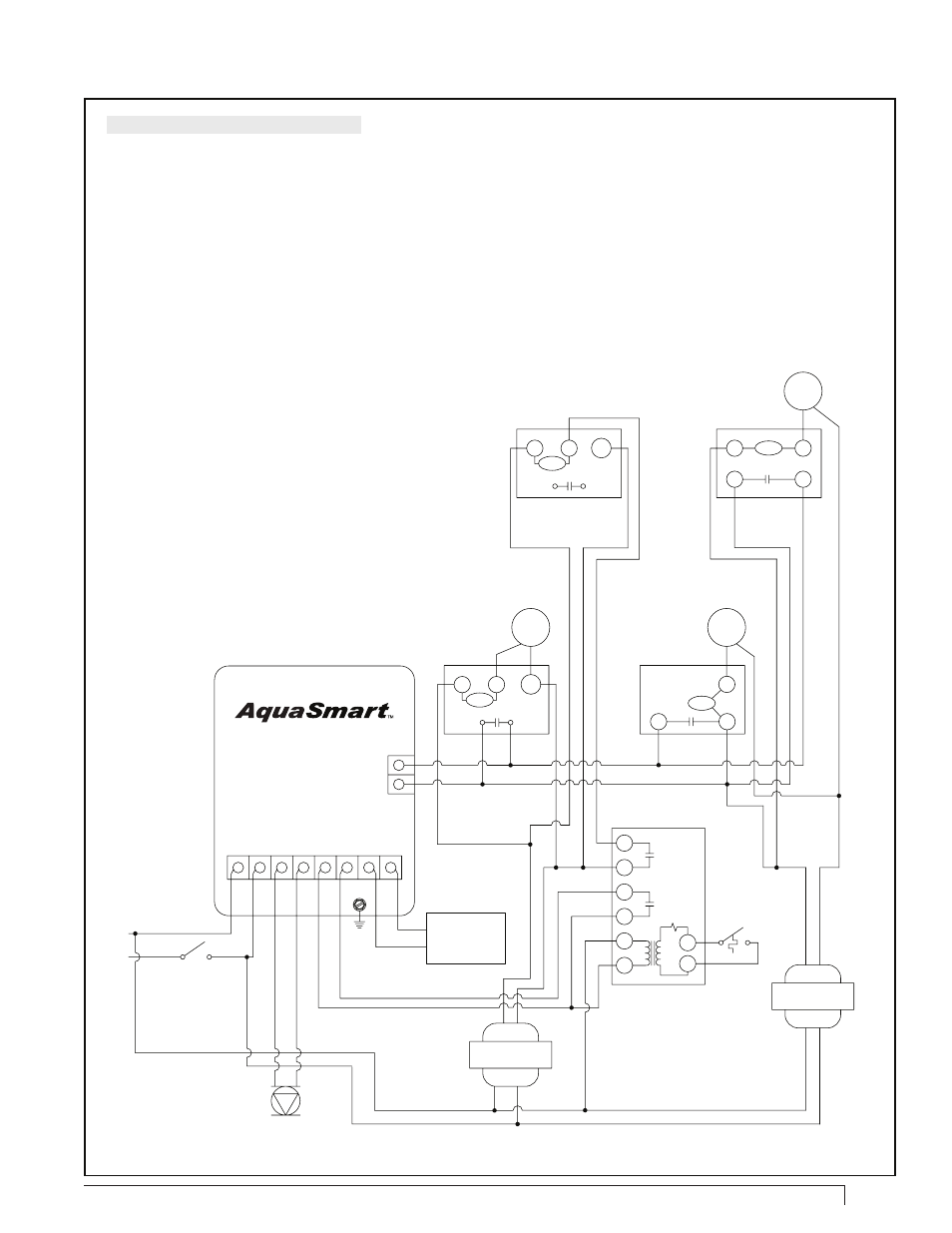
Control Wiring (Option 2): 7600A only
CAUTION - Always observe proper polarity when connecting multiple transformers in a
system (connect red terminal of external transformer to TR terminal of AquaSmart).
1. Set “DHWP on ZR” (see programming section for instructions)
2. Set “C1 on BOTH” (see programming section for instructions)
3. Circulator-on delay will affect all zones. Circulator-off delay will have no effect.
4. 24 VAC zone valves cannot be powered directly
with the 7600A. Add an additional transformer as
shown for every two or less valves.
5. Ensure there are no jumpers between the
terminals of the zone valves.
TH/
TR
TR
TW
ZONE 1
LOW VOLTAGE
THERMOSTAT
ZONE 1
24 VAC
ZONE VALVE
SK10047
L2 L1 C1 C2 ZC ZR B1 B2
NEUTRAL
HOT
120 VAC
BLACK
WHITE
CIRCULATOR
120 VAC
GENERAL
CIRCULATOR
TR
TH
Honewell
V8043F
ZONE
RELAY
T
T
1/H
2/N
3
4
5
6
DHW ZONE
24 VAC
ZONE VALVE
Y
R
R
Y
ZONE 3*
LOW VOLTAGE
THERMOSTAT
ZONE 3*
24 VAC
ZONE VALVE
Honewell
V8043E, V8044E
Taco
550
ZONE 2
24 VAC
ZONE VALVE
ZONE 2
LOW VOLTAGE
THERMOSTAT
TH
TR
DHW
LIMIT
CONTROL
Honeywell
V8043F
MTR
TH/
TR
MTR
MTR
40 VA
TRANSFORMER
3
2
MTR
1
FIELD/MFR.
SUPPLIED
SERVICE
SWITCH
120 VAC
BURNER OR
GAS IGNITION
SYSTEM
40 VA
TRANSFORMER
Figure 17 (continued) - 7600A/B alternate multi-zone
connections with Indirect Domestic Hot Water (DHW)
* Additional zones can be added by duplicating the
plumbing and wiring of zone 3, adding additional
transformers as needed.