Inspect/prepare installation site – Beckett SM User Manual
Page 5
5
SF/SM Burner Manual
Inspect/Prepare
Installation Site
Section: Inspect/Prepare Installation Site
Special Requirements
THE INSTALLATION OF A BURNER SHALL BE IN
ACCORDANCE WITH THE REGULATIONS OF
AUTHORITIES HAVING JURISDICTION.
For recommended installation practices in the U.S.
refer to the latest edition of NFPA 31. (CSA-B139
and CSA-B140 in Canada.
Concealed damage — If you discover damage to
the burner or controls during unpacking, notify the
carrier at once and fi le the appropriate claim.
When contacting Beckett for service information
— Please record the burner serial number (and have
available when calling or writing). You will fi nd the
serial number on the silver label located on the left
rear of the burner. Refer to Figure 1.
○
○
○
○
Professional Service
Required
Incorrect installation, adjustment, and
use of this burner could result in severe
personal injury, death, or substantial
property damage from fi re, carbon
monoxide poisoning, soot or explosion.
Please read and understand the manual supplied with
this equipment. This equipment must be installed,
adjusted and put into operation only by a qualifi ed
individual or service agency that is:
Licensed or certifi ed to install and provide technical
service to oil heating systems.
Experienced with all applicable codes, standards
and ordinances.
Responsible for the correct installation and
commission of this equipment.
Skilled in the adjustment of oil burners using
combustion test instruments.
The installation must strictly comply with all applicable
codes, authorities having jurisdiction and the latest
revision of the National Fire Protection Association
Standard for the installation of Oil-burning Equipment,
NFPA 31 (or CSA-B139 and CSA-B140 in Canada).
Regulation by these authorities take precedence over the
general instructions provided in this installation manual.
y
y
y
y
Fire, Smoke & Asphyxiation
Hazard
Carefully inspect the chimney or exhaust vent system.
Make sure it is properly sized and in good working
condition.
Follow the instructions supplied by the appliance
manufacturer.
The installation must strictly comply with all applicable
codes, authorities having jurisdiction and the latest
revision of the National Fire Protection Association
Standard NFPA 31 for the installation of chimneys
and vent sizing, (or CSA-B139 and CSA-B140 in
Canada).
Regulation by these authorities take precedence
over the general instructions provided in this
installation manual.
y
y
y
y
y
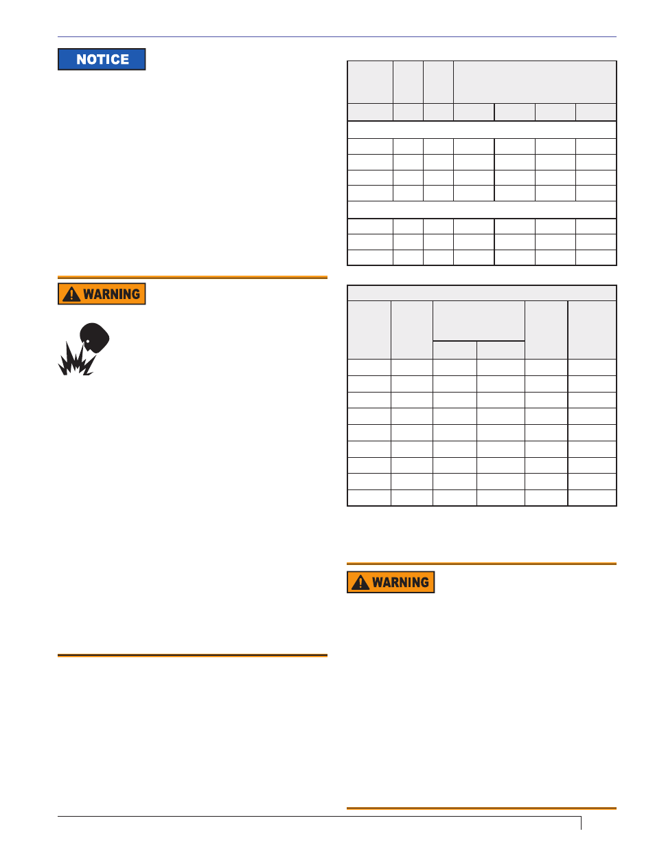
Table 2 – Air Tube Combination (ATC) codes
Firing
Rate
(gph)
Head
Static
plate
size
ATC Codes for usable air tube lengths
(‘A’ in inches; See Figure 3.)
(min-max)
(in.)
6-5/8
9
13
16
SF Burner Only
1.25-2.25
F12
2-3/4
SF65VW
SF90VW SF130VW SF160VW
1.75-2.75
F22
2-3/4
SF65VP
SF90VP
SF130VP SF160VP
1.75-3.25
F220
None
SF65FD
SF90FD
SF130FD SF160FD
2.5-5.5
F310
None
SF65FU
SF90FU
SF130FU SF160FU
SM Burner Only
1.25-2.00
F12
2-3/4
SM65VW SM90VW SM130VW SM160VW
2.00-3.00
F220
None
SM65FF
SM90FF
SM130FF SM160FF
2.00-3.00
F22
None
SM65VM
SM90VM SM130VM SM160VM
Table 3. Chamber Dimensions
Chamber Dimensions (inches)
Firing
Rate
(GPH)
Round
I.D.
Rectangular
Height
Floor to
nozzle
Width
Length
1.25
11
10
11
12
5-6
1.50
12
11
12
13
6-7
2.00
14
12
15
13
6-7
2.50
16
13
17
14
7-8
3.00
18
14
18
15
7-8
3.50
19
15
19
15
7-8
4.00
20
16
21
16
8-9
5.00
23
18
23
18
9-10
5.50
24
19
24
19
10-11