Beckett SM User Manual
Page 10
10
Note: to determine the proper fuel line size, refer to the
fuel pump manufacturer’s instructions provided with
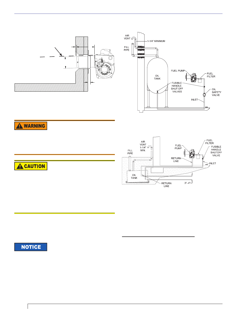
the burner. Refer to Figure 6 or Figure 7 for typical
installation layouts.
Installing the Oil Tank and Supply System
Figure 5. – Mounting Burner in Appliance
Connect fuel lines
Carefully follow the fuel unit manufacturer’s literature
and the latest edition of NFPA 31 for oil supply system
specifi cations (CSA B-139 in Canada).
Fuel supply level with or above burner –
The burner may be equipped with a single-stage fuel
unit for these installations. Connect the fuel supply to the
burner with a single supply line if you want a one-pipe
system (making sure the bypass plug is NOT installed in
the fuel unit.) Manual bleeding of the fuel unit is required
on initial start-up. If connecting a two-pipe fuel supply,
install the fuel unit bypass plug.
Figure 6. – Inside Tank Gravity Feed System
Figure 7. – Outside Buried Tank-Lift System
To further protect the fuel supply
system and reduce nozzle orifi ce
plugging, a dual fi ltration system can be installed. This
typically consists of a 50 micron primary fi lter, located
near the fuel tank and a secondary fi lter rated for at least
10 microns located near the burner.
Section: Mount the Burner/Connect Oil Supply
SK8745
Tilt down 2
°
If space between burner air
tube and opening exceeds
1/2 inch, pack burner
opening with ceramic fiber
refractory.
4”
1/4”
A
7/8”
Oil Leak and Fire Hazard
Install the oil tank following applicable standards in the
U.S. by referring to the latest edition of NFPA 31 or CSA-
B139 & CSA-B140 in Canada, and all authorities having
jurisdiction.
Do Not Use Tefl on Tape
Damage to the pump could cause impaired burner
operation, oil leakage and appliance soot-up.
Never use Tefl on tape on fuel oil fi ttings.
Tape fragments can lodge in fuel line components
and fuel unit, damaging the equipment and
preventing proper operation.
Use oil-resistant pipe sealant compounds.
y
y
y