Rane SP 13 User Manual
Page 2
Manual-2
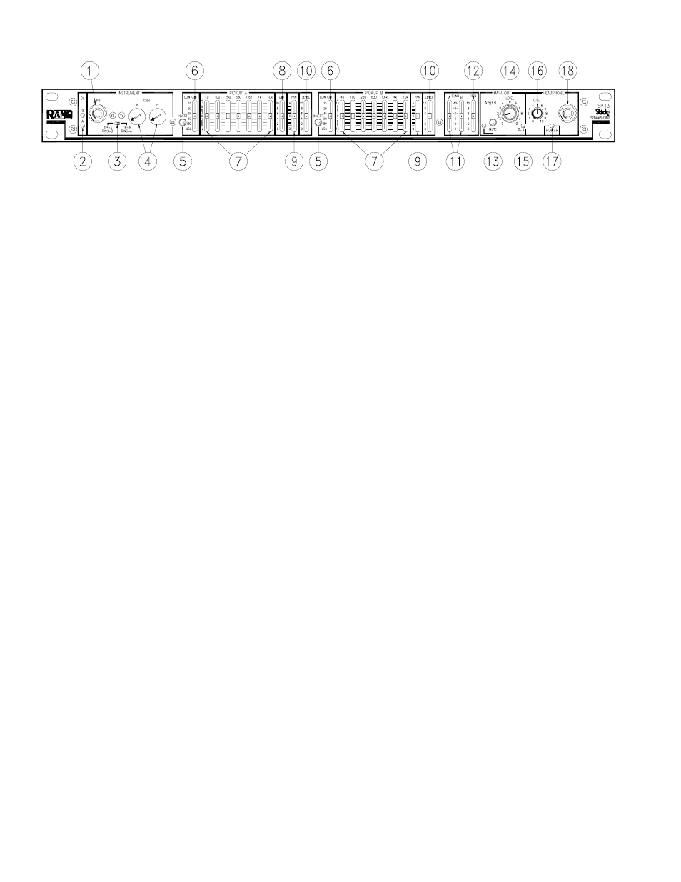
FRONT PANEL DESCRIPTION
ቢ Stick® INSTRUMENT INPUT: is a stereo ¼" TRS (Tip-Ring-Sleeve) INPUT jack for use with a Stick instrument with
two pickups; Use a balanced or stereo ¼" shielded cable to connect your instrument to this Input. However, this also accepts
a mono input. When using a mono cable, signal is routed to the TIP selected by the Input Wiring Switch (see
ቤ).
ባ A & B Input OVERLOAD indicators: are useful in monitoring pickup level and initially in setting PICKUP GAIN TRIM
controls. These indicators light approximately 4 dB before actual clipping, so occasional flickering is okay, but they should
never be allowed to light steadily.
ቤ Input wiring switch: allows choice of Input wiring. Either TIP=A and RING=B, or vice-versa.
ብ Input INSTRUMENT GAIN trims: set the proper Gain for each pickup. Range is from 6 dB minimum to 60 dB maxi-
mum.
ቦ INVERT switches: Invert the polarity (phase) of the A pickup with respect to the B pickup. Either A or B PICKUPS may
be individually Inverted.
ቧ LOW CUT frequency: adjusts the corner frequency of the LOW CUT (high-pass) filter from 15 Hz to 250 Hz. Use to
reduce unwanted low frequencies in either A or B Pickups.
ቨ 7-band graphic equalizer boost/cut controls: set the amount of boost/cut for each of the indicated bands in both Pickups
A and B. A grounded center detent guarantees flat response for filters not used.
ቩ PICKUP A OUT control: adjusts the level of the AUX OUTPUT jack. This Output is independent of the LEVEL and
MAIN OUT LEVEL controls.
ቪ PAN controls: for both PICKUPS A and B allow signal routing anywhere between MAIN OUT A and B.
ቫ LEVEL controls: for both PICKUPS A and B set the overall Level of each signal.
ቭ SEND A/B controls: adjust the amount of signal at each of the SEND jacks (to external signal processing).
ቮ RETURN control: is a “stereo” Return. Controls the amount of A and B entering the RETURN jacks.
ቯ MAIN OUT MUTE button: cuts off the signal to both A and B Main Outputs. Does not affect the Headphone Output. The
red LED indicates Muted Output.
ተ MAIN OUT A & B LEVELS: are concentric controls used to separately set the Main A & B Output Levels.
ቱ MAIN OUT OVERLOAD indicator: monitors both A and B Main Outputs. An overload condition (within 4 dB of
clipping) on either Output causes this red indicator to light.
ቲ HEADPHONE LEVEL: controls the volume of the HEADPHONE Output jack.
ታ POWER indicator: glows yellow when the proper power supply is connected and powered.
ቴ Headphone jack: Accepts standard stereo headphones rated from 32-600 ohms equipped with a ¼" TRS plug.