Front panel description – Rane RC 24A User Manual
Page 2
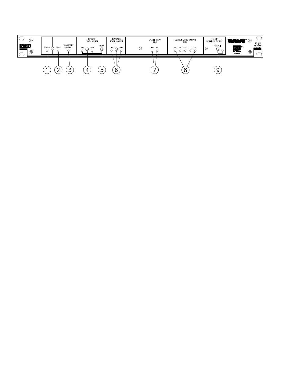
FRONT PANEL DESCRIPTION
1. POWER LED. When dim, this LED indicates that you forgot to plug in the RC-24A.
2. SYNC LED. Indicates that a suitable AES/EBU (or SPDIF) sync source is plugged in. If this LED is not lit, the RC-24A is
not receiving signal from a source. Check the INPUT SELECT switch to make sure the proper input is selected.
3. TRANSPORT PRESENT LED . When lit, this LED indicates that an ADAT is connected to the RC-24A via the fiber optic
interface.
4. RECORD TRACK ASSIGN BUTTON . This push button switch lets you select which four tracks of the ADAT are
recorded with the stereo 24-bit digital audio source signal. An LED indicates whether you are recording onto tracks 1-4 or
5-8.
5. RECORD TRACK ASSIGN “BOTH” BUTTON . This push button selects all 8 tracks for recording, no matter what the
state of the RECORD TRACK ASSIGN BUTTON (previous section) is. Tracks 1-4 are identical to tracks 5-8. Use this
option when you are archiving a stereo master, and wish to create a redundant copy on the same tape.
6. PLAYBACK TRACK ASSIGN BUTTON . This push button switch lets you select which four tracks of the ADAT are
converted back to 24-bit digital audio, and transmitted out the AES/EBU OUTPUT. An LED indicates whether you are
playing tracks 1-4 or 5-8.
7. SAMPLE RATE LEDS . These LEDs indicate the sample rate of the AES/EBU (or SPDIF) source (sync) input (44.1kHz or
48kHz).
8. SOURCE WORD LENGTH LEDS . These LEDs indicate the word length (in bits) of the AES/EBU (or SPDIF) source
(sync) input.
9. 16-BIT DITHERED OUTPUT ENGAGE SWITCH. This switch engages 16-bit dithering and truncation on the AES/
EBU OUTPUT. Dither should be engaged when the AES/EBU OUTPUT is feeding a device that truncates the signal to 16
bits (e.g. DAT recorder, digital signal processors, and so on).