Rane MM 8x User Manual
Page 2
Manual-2
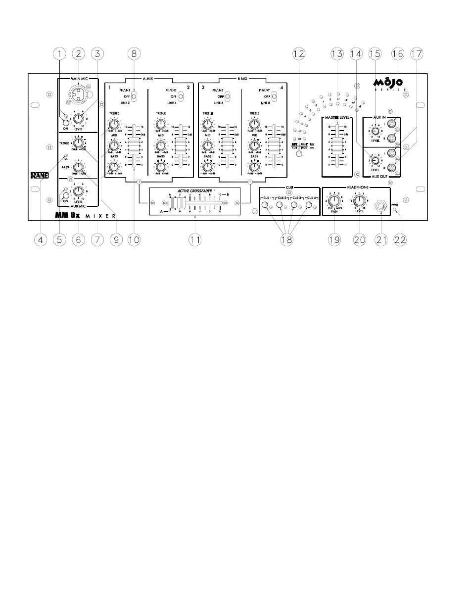
FRONT PANEL DESCRIPTION
1. MAIN MIC ON switch: This switch puts the Main Mic signal into the mixer signal path. When the switch is pressed in, the
Main Mic is on and the adjacent red LED blinks.
2. Front panel MAIN MIC input: This 3-pin XLR input connects a balanced microphone. A parallel Main Mic input is on the
rear of the unit. Do not connect microphones to both front and rear Main Mic inputs.
3. MAIN MIC LEVEL control: This control adjusts the level of the Main Mic input.
4. MIC OVERLOAD indicator: This red LED monitors both microphone signals, before and after Mic EQ. It lights when the
signal exceed the Mic section’s output capability (3 dB below clipping). Occasional flickering is acceptable; however,
steady lighting requires a reduction in the Mic LEVEL control to prevent distortion.
5. AUX MIC ON switch: This switch puts the Aux Mic signal into the mixer signal path. The adjacent red LED blinks when
the switch is pressed in, indicating that the Aux Mic is on.
6. AUX MIC LEVEL control: This control adjusts the level of the Aux Mic input.
7. MIC EQ: These controls are used to contour the frequency response of the summed Main and Aux Microphone inputs.
8. Source Input Select switch: This switch selects either a Phono/Line or Line input for the channel. In the center position the
channel input is muted.
9. Source EQ: These controls are used to contour the frequency response of the selected source input.
10. Source Input fader: This fader controls the level of the input selected for the channel.
11. ACTIVE CROSSFADER: This fader controls the relative output level from the summed A and B mixes. When the fader
is at its far left, only the A mix is heard from the outputs. As the fader is moved toward the right, the amount of B mix is
increased and the amount of A mix is decreased. When the fader is centered, equal amounts of A and B mixes are routed to
the outputs. Fully right is all B mix at the outputs.