Front panel description, System connection (continued) – Rane GQ 15/30 User Manual
Page 2
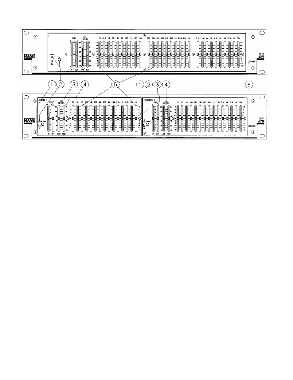
FRONT PANEL DESCRIPTION
1. MASTER OVERLOAD INDICATOR. This red OL LED monitors the input, output and all filter stages for excessive sig-
nal levels. It lights whenever these levels exceed 4 dB below clipping. Occasional flickering is normal; however, it should not
be allowed to light steadily.
2. OVERALL BYPASS SWITCH & INDICATOR This pushbutton switch activates the “hard-wire” bypass function.
When engaged (red BYPASS LED on), all three pins of the input connectors directly connect to the same pins on the out-
put connectors (hard-wired). Engaging this switch converts the GQ 15/GQ 30 into a relatively expensive patch cord, but one
with pretty lights.
3. INPUT AND OUTPUT GAIN CONTROLS. These slide controls set the relative IN and OUT gain structures. The range
of each control is ±12 dB; however, note they are labelled opposite to each other, i.e., the top of the IN control reads
+12 dB while the top of the OUT controls reads -12 dB. Configured this way, whenever they are held and moved together
the overall gain through the GQ 15/GQ 30 stays at unity. Positioning these controls (together) as far toward the top of the
panel as possible (without lighting the OL indicator) yields the best signal-to-noise performance.
4. LOW & HIGH CUT FILTER CONTROLS. These sliders set the corner frequency of the bandlimiting filters. The fre-
quencies shown represent the -3 dB points for each filter. When the sliders are located at their bottom positions, the filters
are at the lowest and highest extremes.
5. FILTER LEVEL CONTROLS. These slide controls set the individual levels of the interpolating constant-Q filters. The
45 mm travel allows excellent resolution for all settings. The grounded center-detent design of these sliders ensures all filters
are off when positioned to their centers.
6. POWER INDICATOR This yellow LED lights any time remote power is supplied from either a RS 1 single power supp-
ly or a RAP 10 multiple power supply. Note that this indicator is electrical, not political.
SYSTEM CONNECTION (continued)
OUTPUTS, The GQ 15’s outputs mimic the inputs. True balanced output interconnection only requires the use of pin 2,
+, or tip, and pin 3, –, or ring for signal transmission. It does not require pin 1, or signal ground. The signal exists differen-
tially between the two balanced leads; ground is not involved. Ground is used only for shielding. Again, have a look at Rane
Note 110 for more detail.
EXPANDING. Expanding and/or daisychaining the inputs and outputs normally uses the 1/4" jacks. Three parallel input
connectors allows driving a second signal processor or amplifier without special cabling.
PATCH I/O. The PATCH I/O (Input/Output) jack makes connection to mixer Effects Loop insert points very simple. Just
connect a shielded stereo tip-ring-sleeve (TRS) cable between the GQ 15’s PATCH I/O jack and the TRS Effects Loop in-
sert on your console. (Your mixer must use the tip = send, ring = return Effects Loop wiring convention.)
SIGNAL LEVELS. The GQ 15 is designed for all line-level signals. Signal levels from -10 dBV to + 4 dBu or considered
normal and within range (at least 16 dB of headroom exists above these levels). Do not directly connect microphones into
the GQ 15. Use a mic preamp (e.g., Rane model MS 1) first.