Ge60man.pdf, Operators manual ge 60 – Rane GE 60 User Manual
Page 3
Manual-
OPERATORS MANUAL
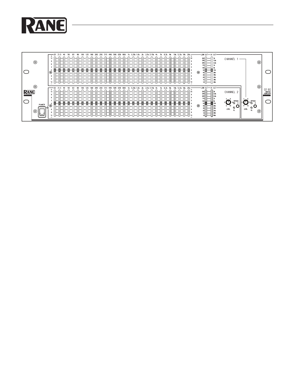
GE 60
GRAPHIC EQUALIZER
QUICK START
Okay, Know-it-all. So you don’t need to read the manual. Well do your mother a favor and read this section. You don’t have to
read anything else. Ever. Now turn MTV off.
Hook-up is intuitive. Just follow the silkscreened instructions on the rear of the unit. All three Inputs are wired in parallel (they
do not sum, smarty pants); and all three Outputs are wired in parallel. Use any one Input and any or all Outputs. Polarity convention
is per IEC/ANSI/AES standards of pin 2 positive, pin 3 negative and pin 1 shield. The GE 60 does not invert the signal.
Set the LO CUT and HI CUT controls as necessary to restrict bandwidth. Full frequency response results from positioning them
all the way to the bottom.
Anyone familiar with other graphic equalizers finds the GE 60 just as familiar. Setting curves is as easy as it is on all Rane graph-
ics thanks to our innovative interpolating constant-Q circuitry. If you feel you want more information on setting up your curves,
please see the back page.
OK, MTV back on, I'm outta here.
GE 60 CONNECTION
When first connecting the GE 60 to other components, leave
the power switch off until the very last. This gives you a chance to
make mistakes and correct them without damaging your fragile
speakers, ears and nerves.
INPUTS
All three Inputs are wired in parallel and are actively bal-
anced. Each works equally well, but use only one, they do not
sum. Choose strictly from a required hardware point-of-view,
there will be no performance trade-offs. The wiring conven-
tion adheres to American, British and International standards
of pin 2, or tip being hot, pin 3, or ring being return, and pin
1, or sleeve being shield. It is not necessary to short any Inputs
to ground—it doesn’t hurt, it’s just not necessary. Use pin 1, or
the shell, for shield ground. Unbalanced operation involves us-
ing only pin 2, or tip as signal and pin 1, or sleeve as shield and
ground.
OUTPUTS
The Outputs mimic the Inputs. Balanced output requires
using pin 2, or tip, and pin 3, or ring for the signal. It does not
require pin 1 or shield. The signal exists differentially between
the two balanced leads; ground is not involved. For hum-free
systems ground is used only for shielding. Unlike the Inputs, you
may use multiple Output jacks simultaneously to drive different
devices.
EXPANDING
Expanding and/or daisychaining the Inputs and Outputs
normally uses the ¼" jacks. Three parallel Input connectors
allows driving a second signal processor or amplifier without
special cabling.
SIGNAL LEVELS
Signal levels from –10 dBV to +4 dBu are considered normal
and within range (at least 20 dB of headroom exists above these
levels). Do not directly connect microphones into the GE 60.
These require a mic preamp.
WEAR PARTS:
This product contains no wear parts.