Front panel description – Rane FSC 22 User Manual
Page 2
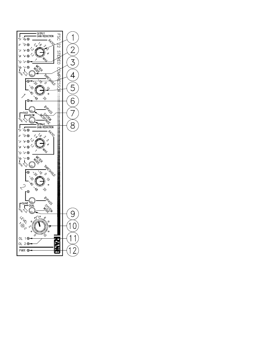
FRONT PANEL DESCRIPTION
1. RATIO CONTROL. This rotary control determines the slope of the compressor for
signals exceeding threshold. Full counter-clockwise rotation of the RATIO control
disables all Compressor activity.
2. DUAL FUNCTION METER. This six segment LED meter indicates either Gain
Reduction or Output Level as determined by the position of the Meter Mode
Switch. GAIN REDUCTION mode displays the amount of reduction (below
unity) applied to the audio signal by the VCA. OUTPUT mode displays the
balanced output level in dBu, i.e. where 0dBu = 0.775 Vrms.
3. METER MODE PUSHBUTTON. The out, or disengaged, position selects GAIN
REDUCTION meter mode. The in, depressed, or engaged, position selects
OUTPUT meter mode.
4. THRESHOLD LED. This yellow LED illuminates any time the input signal
exceeds the THRESHOLD setting.
5. THRESHOLD CONTROL. The position of this rotary knob determines above
what input level the Compressor/Limiter functions.
6. BYPASS LED. A red LED indicating the BYPASS switch is engaged.
7. BYPASS SWITCH. A passive switch used to bypass all active circuitry in this
channel. Press in to Bypass. Useful for A-B comparisons and to restore signal path
should power fail.
8. SYSTEM RESPONSE SWITCH. Use this pushbutton to select the desired attack/
release response. Out chooses SLOW; in chooses FAST.
9. SYSTEM MODE SWITCH. In the in (SLAVE) position, this switch causes both
Channels’ Compressors to act together, i.e., they are “slaved”. All controls for both
Channels remain active, so independent settings are still possible; however,
whenever a signal in either Channel exceeds its setting, then both Channels change
by the same amount. In the out (DUAL) position, both Channels operate indepen-
dently.
10. OUTPUT LEVEL CONTROLS. This concentric control increases or decreases
the output Level for each Channel. Up to 10dB of gain is available. Unity gain is
about “7” for balanced outputs, and “8” for unbalanced outputs.
11. OVERLOAD LEDS. Illuminates any time either output signal gets to within about
4dB of clipping. Occasional flickering is okay, continuous is not.
12. POWER INDICATOR LED. Hey, if it’s lit, you’re fit; if not, call a doc. And
while we’re on the subject of power, let me take this opportunity to tell you just
what I think about runaway government ...