Front panel description – Rane FPE 13 User Manual
Page 2
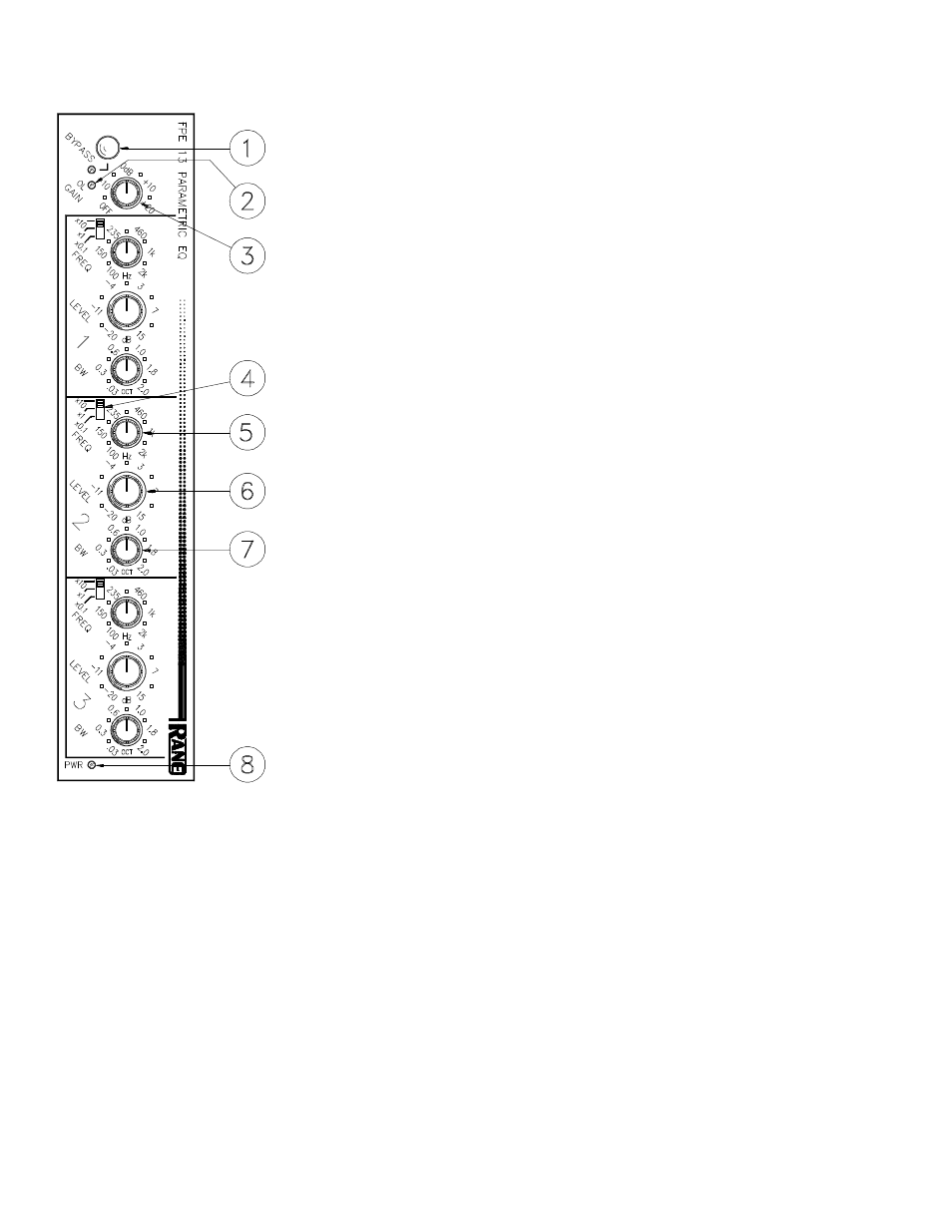
FRONT PANEL DESCRIPTION
1. OVERALL BYPASS SWITCH & INDICATOR. This pushbutton switch activates
the “hard-wire” bypass function. When in its in position, all three pins of the Input
connector(s) are directly connected to the same pins on the Output connector(s) and
the red LED lights. Engaging this switch converts the FPE 13 to a relatively expen-
sive patch cord with pretty lights.
2. MASTER OVERLOAD INDICATOR. This red LED illuminates whenever the
input, output, or any of the three parametric filters exceeds a level of 4dB below
clipping. Occasional flickering is normal; however, it should not be allowed to light
steadily.
3. INPUT GAIN CONTROL. This rotary control increases INPUT gain as it is rotated
clockwise. Its range is from OFF at full CCW rotation to +20dB at full CW.
4. FREQUENCY RANGE SWITCH. The calibrations on this three position switch
indicate the factor by which the frequency calibrations of the Frequency sweep
control (5) should be multiplied. For instance, if the range switch is in the “x0.1”
position and the sweep knob is at 460, then the actual center frequency of the filter is
46Hz. The proper operation of this switch in conjunction with the sweep control
yields a range of 10Hz to 20kHz.
5. FREQUENCY SWEEP CONTROL. This rotary control increases the center
frequency of its filter as it is rotated clockwise. It is calibrated from 100 to 2k, and its
exact frequency is determined by the range switch described in (4), above.
6. FILTER LEVEL CONTROL. This rotary control determines the amount of boost
or cut applied to the FPE’s passband by its filters. The center detent, cleverly placed
at the center of rotation of this control, provides a ground for the filter which com-
pletely eliminates the filter’s influence over FPE 13 operation. Rotating this knob
clockwise increases the gain at the center frequency of the filter, CCW from center
decreases the gain at said center frequency.
7. FILTER BANDWIDTH CONTROL. Calibrated from .03 octaves to 2.0 octaves,
this rotary control adjusts the “width” of coverage of each filter. .03 octave (1/30
octave) will yield the narrowest coverage. Bandwidths this narrow are normally
reserved for notch feedback control. Higher settings yield smoother curves and are
convenient for program sweetening and acoustic compensation.
8. POWER LIGHT. This yellow LED illuminates any time power is supplied to the
FPE 13 from a Rane RS 1 or VC 18 single power supply, RAP 10 or FRS 8 multiple
power supply. Other power sources could conceivably cause illumination of the LED
and several ICs and resistors inside.