Front panel description – Rane FDA 18 User Manual
Page 2
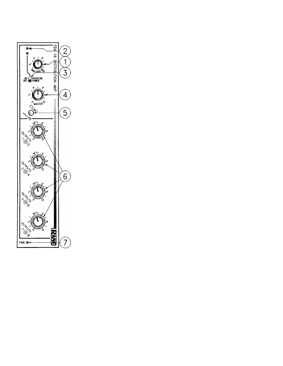
FRONT PANEL DESCRIPTION
7. POWER INDICATOR. When this little yellow LED illuminates, the foregoing informa-
tion applies. If darkness persists at this location — ignore the above. Pity.
6. OUTPUT LEVEL CONTROLS. These concentric controls set each individual output
level. The inner knobs are for odd numbered channels, and the outer knobs are for even
numbered channels.
5. MIC/LINE SWITCH. In the out position, the input is scaled for microphone input lev-
els. In the depressed position, the input stage is set for line-level input.
4. MASTER LEVEL CONTROL. This control sets the signal level appearing on the inter-
nal distribution bus. Output levels may be selected via the four pairs of concentric controls
connected to the output sections. This is true, however, only if the internal PRE/POST
switches are in the POST position (as shipped).
In the PRE position, the MASTER level control is bypassed for that respective output
and only the input GAIN control and the individual OUTPUT level control has any affect.
3. PHANTOM POWER SWITCH AND INDICATOR. In the ON position (LED on),
15 VDC phantom power appears on each input terminal on the rear of the module.
2. OVERLOAD INDICATOR. This red LED illuminates whenever the combination of
input level and input gain adjustment causes the input amplifier to reach or exceed a level
equal to 4 dB below clipping.
1. INPUT GAIN CONTROL. This control sets the gain of the input. The adjustment
MIN to MAX range is from 26 dB to 70 dB when MIC is selected, and from -7 dB to 37 dB
for LINE sources. Set the highest level that does not cause the OL indicator to come on
continuously.