Manual-2 front panel description – Rane DC 24 Manual User Manual
Page 2
Manual-2
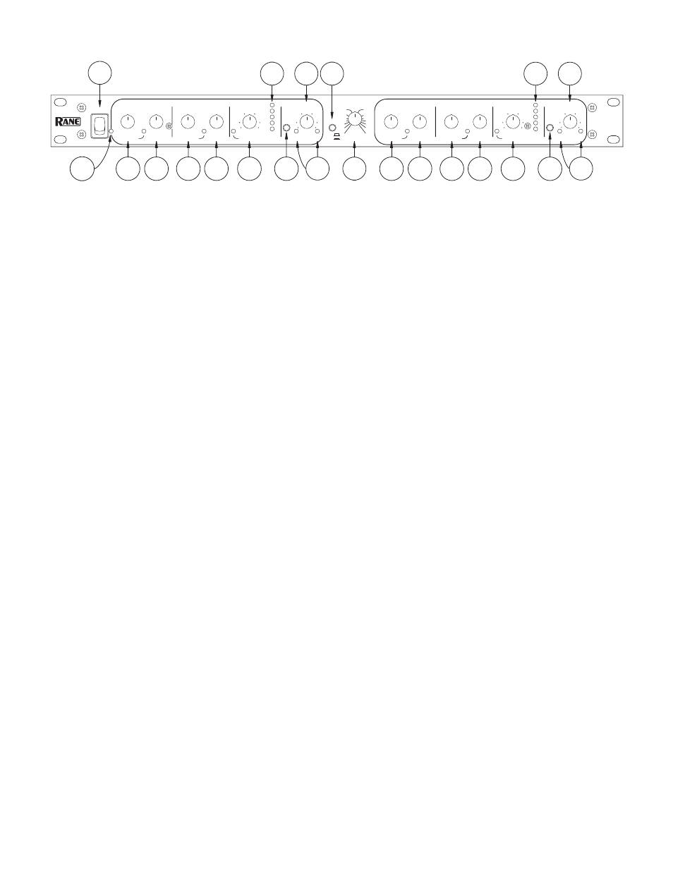
FRONT PANEL DESCRIPTION
1
POWER switch:
It has been a tradition at Rane Corporation to say something clever about the POWER switch on all its prod-
ucts. Certain government restrictions now eliminate our option of continuing this tradition. Pity.
2
POWER indicator LED:
This solid-state yellow illumination device lights up to let the operator know Item 1 (above) is working
and the thing is plugged in.
3
GATE / EXPANDER THRESHOLD control:
allows the operator to set the input level below which the Gate/Expander oper-
ates. The LED illuminates yellow any time the input signal falls below the threshold level set by this control.
4
GATE / EXPANDER RATIO control:
determines the Ratio to be applied to the Gate/Expander function. Increased clockwise
rotation increases the circuit slope. The full counter-clockwise position disables the Gate/Expander.
5
COMPRESSOR THRESHOLD control:
determines above what input level the Compressor functions. Full clockwise rotation
disables the Compressor entirely. The LED illuminates yellow any time the input signal exceeds the threshold level set by this
control.
6
COMPRESSIOR RATIO control:
determines the slope of the Compressor once it has exceeded the indicated threshold. Full
counter-clockwise rotation of the RATIO control disables all Compressor activity.
7
LIMITER THRESHOLD control:
determines above what level the Servo Locked Limiter™ functions. Full clockwise rotation
of this knob disables all Limiter activity. The LED illuminates red any time the input exceeds the LIMITER THRESHOLD set-
ting.
8
GAIN REDUCTION meter:
indicates the amount of reduction, below unity, being applied to the audio signal by the VCA.
9
BYPASS switch:
When pressed in, this channel in the DC 24 is is hard-wire Bypassed. Each channel may be individually By-
passed for comparison and alignment purposes. See OPERATING INSTRUCTIONS on page Manual-4.
0
OUTPUT LEVEL control:
increases or decreases the output gain of each channel by 12 dB. In the center detent, gain will be
unity. (NOTE: Channel 2 OUTPUT LEVEL controls overall output in COMBINE mode.)
q
SIGnal present LED:
illuminates any time the input signal exceeds approximately -40 dBu.
The OverLoad LED: illuminates any time the output exceeds a level equal to -4 dB below the clipping level.
w
DUAL / SLAVE mode switch:
In the in (SLAVE) position, this switch causes both channels’ Gate, Compressor and Limiters to
act together, i.e., they are “slaved.” All controls for both channels remain active, so independent settings are still possible; how-
ever, whenever a signal in one channel exceeds its settings, then both channels change by the same amount. In the out (DUAL)
position, both channels operate independently.
e
CROSSOVER FREQUENCY control:
This rotary control selects the crossover frequency. What did you think?
3
4
5
6
7
9
11
2
1
8
10 12
3
4
5
6
7
9
11
8
10
13
DC 24
THRESHOLD
THRESHOLD
RATIO
THRESHOLD
RATIO
SIG LEVEL OL
BYPASS
MODE
FREQUENCY
POWER
GATE
COMPRESSOR
CH 1 OUTPUT
LIMITER
CROSSOVER
GAIN
REDUCTION
THRESHOLD
THRESHOLD
RATIO
THRESHOLD
RATIO
SIG LEVEL OL
BYPASS
GATE
COMPRESSOR
CH 2 OUTPUT
LIMITER
GAIN
REDUCTION
LOW
EXPANDER
(:1)
(:1)
SLAVE
DUAL
DYNAMIC
CONTROLLER
-50
10
-40
2
-30
-20
3
-10
1
10
1
10
8
6
4
7
5
1.1
4
1.2
1.4 1.6 2
3
-6
24
12
+6
0
6
3
-40
-30
-20
10
0
+12
-12
+6
-6
0
HIGH
EXPANDER
(:1)
(:1)
24
12
6
3
0
7k
200
70
100
75
90
150
125
400
2k
800
1.2k
+20
-20
-6
+6
0
+20
-20
-6
+6
0
+12
-12
-10
20
-48
2
3
1
10
8
6
4
7
5
-50
10
-40
-30
-20
0
-10
(:1)
1
10
1.1
4
1.2
1.4 1.6 2
3
-40
-30
-20
0
10
-10
20
-48
6k
4k
0
0