Da 216a, Distribution amplifier data sheet-3 applications, Block diagram – Rane DA 216a (1999 version) User Manual
Page 3
DA 216a
DISTRIBUTION AMPLIFIER
Data Sheet-3
Applications
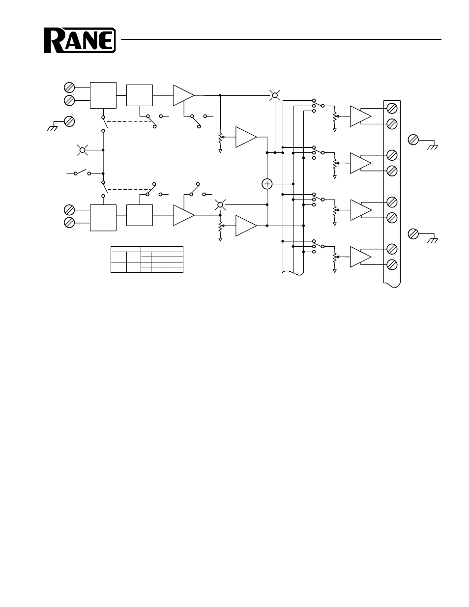
Use of the DA 216a is straightforward. Connect balanced
inputs to the Input screw terminals. Follow the silk-screened
labels to the balanced Output screw terminals. The terminals
accept standard 8 millimeter (#6) spade lugs. Bare wire is
acceptable by twisting the strands, inserting under the
integrated square washer and tightening the screw.
The diagram shows the uncomplicated nature of the
DA 216a. Fully balanced low-noise mic preamplifiers receive
the signal to be split or distributed. The Input Pad pushbuttons
change the input gain range. Additional Gain pushbuttons
increase either Mic or Line level inputs another +20 dB (see
table above).
Keep an eye on the Overload indicators when setting the
gain. Always use the most gain possible without causing the
Overload indicator to light. Occasional flickering is permit-
ted. Setting gain this way maintains the best signal-to-noise
performance for the system. The Master Level controls allow
level matching and balancing as required.
When operating unbalanced, a 6 dB loss of signal must be
taken into account when setting the gain structure of the
system. When wiring an Output for unbalanced operation do
not ground the unused terminal (i.e. usually the “–”).
Unbalanced uses only the “+” and ground terminals.
32 Unbalanced Outputs Tip: The (“–”) Output may also
be used as an unbalanced line driver, albeit inverted. The
balanced Input terminals of the next stage must be reversed
(+) for (–) to correct for the inversion. This nets a total of 32
Outputs! However, the penalty for 32 outputs is that unbal-
anced operation will not drive long lines and individual
control is lost.
Block Diagram
+10 dB
+10 dB
POWER
PHANTOM
INPUT
PROTECT
RFI/EMI
20 dB
PAD
ESD
OL
INPUT
PROTECT
RFI/EMI
ESD
OL
INPUT A
INPUT B
15V
GND
GND
R
R
GAIN
20 dB
PAD
MIC/LINE
PAD
INPUT
INPUT
LEVEL B
MASTER
GAIN
MIC/LINE
PAD
INPUT
INPUT
LEVEL A
MASTER
GND
GND
GND
GND
A
A+B
B
SELECT
OUTPUT
LEVEL
+6dB
+6dB
+6dB
+6dB
OUTPUT 1
OUTPUT 2
OUTPUT 3
OUTPUT 4
+
_
+
_
+
_
+
_
TO OUTPUTS 5 - 16
+
–
+
–
INPUT PAD
GAIN
NET GAIN
IN
OUT
IN
OUT
20 dB
40 dB
40 dB
60 dB
0 dB
+20 dB
+40 dB
+60 dB
-20dB
IN
(LINE)
OUT
(MIC)
0dB