Rane AC 22B (1998 version) User Manual
Page 2
Manual-2
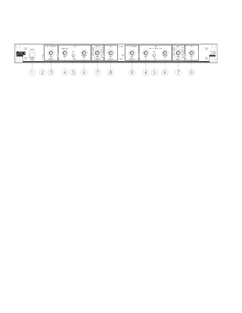
FRONT PANEL: STEREO 2-WAY CONFIGURATION
Observe the labels screened above the controls for stereo operation.
ቢ POWER switch: Self-evident.
ባ POWER indicator: When this yellow LED is lit the unit is ready to operate.
ቤ CHANNEL 1 MASTER LEVEL controls the overall Level of Channel 1 without altering the relative settings of the HIGH
and LOW Outputs. Unity gain for all LEVEL controls is at “7”.
ብ LOW LEVEL controls the Level of signal going to the LOW Output in this Channel. In the MONO SUB mode the Channel
1 LEVEL control sets the Level of the MONO SUB Output, Channel 2's LEVEL control is inactive.
ቦ LOW MUTE: When pressed to the in position, all signal is removed from the LOW Output. This eases tune-up procedures,
as described on pages Manual-7 through 13. In the MONO SUB mode, the Channel 1 LOW MUTE switch mutes the
MONO SUB Output, Channel 2's MUTE is inactive.
ቧ LOW TIME DELAY control adds from 0 to 2 ms of time Delay to the LOW OUT only. This allows a low frequency driver
to be electronically phase-aligned with a high frequency driver whose diaphragm is situated behind the low frequency
diaphragm. Refer to Time Delay Adjustment on page Manual-6. NOTE: Both DELAY controls are inactive in the MONO
SUB mode.
ቨ LOW/HIGH FREQUENCY: This 41-detent selector determines the crossover Frequency between the LOW and HIGH
Outputs. The detents assure maximum accuracy and consistency between Channels. Refer to Selecting Crossover Frequen-
cies on page Manual-6 to determine the proper setting for your particular system.
ቩ HIGH LEVEL controls the Level of signal going to the HIGH Output in this Channel.
ቪ CHANNEL 2 MASTER LEVEL controls the overall Level of Channel 2 without altering relative settings of the HIGH and
LOW Outputs.