Rane AC 22 (1993 version) User Manual
Page 2
Manual-2
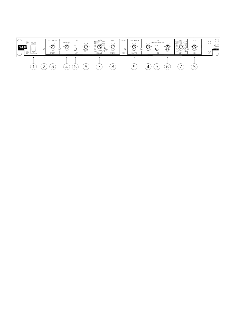
FRONT PANEL: STEREO 2-WAY CONFIGURATION
Observe the labels ABOVE the controls for Stereo operation.
ቢ POWER switch: Self-evident.
ባ POWER indicator: When this yellow LED is lit the unit is ready to operate.
ቤ CH 1 MASTER LEVEL control: sets the overall level of Channel 1 without altering the relative settings of the HI and
LOW outputs. Unity gain for all level controls is at “7”.
ብ LOW frequency LEVEL control: sets the level of signal going to the Low Output in this Channel. Refer to alignment
instructions on page Manual-11. In the MONO SUB mode the Channel 1 LEVEL control sets the Level of the mono
subwoofer output; Channel 2's LEVEL control is inactive.
ቦ LOW frequency MUTE switch: When pressed to the in position, all signal is removed from the Low Output in this
Channel. This eases tune-up procedures as described on page Manual-6. In the MONO SUB mode, the Channel 1 LOW
MUTE switch Mutes the MONO SUB Output, Channel 2's Mute is inactive.
ቧ LOW frequency time DELAY control: adds from 0 to 2 ms of time Delay to the Low Output only. This allows a low
frequency driver to be electronically phase-aligned with a high frequency driver whose diaphragm is situated behind the low
frequency diaphragm. NOTE: Both DELAY controls are inactive in the MONO SUB mode. See instructions on page Manual-6.
ቨ Crossover frequency selector: This 41-detent selector determines the crossover frequency between Low and High fre-
quency Outputs. The detents assure maximum accuracy and consistency between channels. Refer to page Manual-6 to
determine the proper crossover frequency for your particular system.
ቩ HIGH frequency LEVEL control: sets the Level of signal going to the High Frequency Ouput in this Channel.
ቪ CH 2 MASTER LEVEL control: sets the overall Level of Channel 2 without altering relative settings of the HIGH and
LOW Outputs.
Observe the labels ABOVE the inputs and outputs for Stereo operation.