Clearance to combustibles, Framing and finishing, Final finishing hearth – Vermont Casting DVRSR User Manual
Page 5: Gas inlet & manifold pressures, Gas specifications
- 5 -
Do not use this fireplace if any part of it has
been under water. Immediately call a qualified
service technician to inspect the fireplace and
replace any part of the control which has been
under water.
Fig. 4
Fig. 3
Rear ........ 0 mm/0 inches
Floor ........ 0 mm/0 inches
Top .......... 0 mm/0 inches
Front & Side Glass 36" (914mm) to
parallel wall
Side Glass to adjacent wall 3" (76mm)
CLEARANCE TO COMBUSTIBLES
1.
Choose fireplace location.
2.
Place fireplace into position and secure to floor with
1-1/2" screws, or nails. The holes to secure the
fireplace to the floor are located just behind the
access door grill on the left and right hand side of the
fireplace.
3.
Frame in fireplace with a header across the top. It is
important to allow for finished face when setting the
depth of the frame.
4.
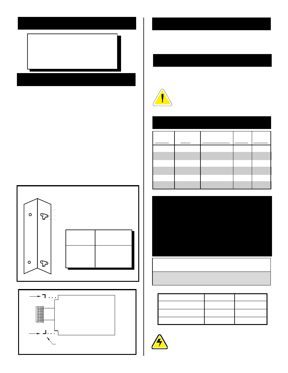
Attach fireplace to frame using adjustable frame
drywall strips(located behind access door for
shipping). Preset depth to suit facing material
(adjustable to 1/2" , 5/8" or 3/4" depths). Fig. 3.
5.
Screw through slotted holes in drywall strip and
then screw into pre-drilled holes on fireplace side.
Measure from face of fireplace to face of drywall
strip to determine final depth. (Fig. 3 & 4)
FRAMING AND FINISHING
ADJUSTABLE DRYWALL STRIP, NAILING FLANGE
1/2", 5/8" AND 3/4" SPACING
Cold climate installation recommendation:
When installing this unit against a non-
insulated exterior wall or chase, it is
mandatory that the outer walls be insulated
to conform to applicable insulation codes.
Non-combustible materials such as brick and tile can be
extended over the outer face of the unit
(Do not cover
louvres or glass door).
FINAL FINISHING
HEARTH
A hearth is not mandatory but it is recommended for
aesthetic purposes. We recommend a non-combustible
hearth which does not obstruct louvre opening.
MAX.
MIN.
INPUT
INPUT
MODEL
FUEL
GAS CONTROL
B.T.U.H
B.T.U.H.
DVRS3RN
Natural Gas
Millivolt Hi/Lo
34,000
23,800
DVRS3RP
Propane Gas
Millivolt Hi/Lo
34,000
25,500
DVRSL RN
Natural Gas
Millivolt Hi/Lo
34,000
23,800
DVRSL RP
Propane Gas
Millivolt Hi/Lo
34,000
25,500
DVRSR RN
Natural Gas
Millivolt Hi/Lo
34,000
23,800
DVRSR RP Propane Gas
Millivolt Hi/Lo
34,000
25,500
GAS INLET & MANIFOLD PRESSURES
Input Minimum
Input Maximum
Manifold Pressure
NATURAL
LP (Propane)
11" wc
13" wc
10" wc
4.5" wc
7" wc
3.5" wc
ADJUSTABLE DRYWALL STRIP
(NAILING FLANGE)
C
A
B
SCREW
POSITION
A
B
C
DRYWALL
DEPTHS
1/2" / 13mm
5/8" / 16mm
3/4" / 19mm
DVRS3 / DVRSL / DVRSR
CERTIFIED TO
ANSI Z21.88-1998 / CSA 2.33 - M98
Vented Gas Fireplace Heaters
The installation of your Majestic Fireplace
must conform with local codes, or in the
absence of local codes, with National Fuel
Gas Code, ANSI Z223.1 — latest edition, or
CAN 1 B1-149.1 and .2 Installation Code.
(EXCEPTION: Do not derate this appliance
for altitude. Maintain the manifold pressure
at 3.5 inches W.C. for Natural Gas and 10
inches W.C. for LP gas.)
GAS SPECIFICATIONS