G and l temperature switches, Temperature switches, Thermowells – Pilgrim MULTIFUNCTION PRESSURE AND TEMPERATURE SWITCHES User Manual
Page 6: Which can be used with 2
6
NOTES:
1. Switches may generally be set between 15% and 100%
of nominal range on increasing or decreasing
temperature. Consult factory for applications where
setpoints must be lower.
2. All deadbands are given in
O
F.
TEMPERATURE RANGE SELECTION
3. Deadbands for LTA and GTA are
adjustable between the values shown.
4. Deadbands for LTS, GTS, LTD and GTD
models are fixed within the range of values shown.
Manufacturing and parts variances result in variation
from one unit to another.
Approximate Deadband
(2)
Nominal Range
Max.
LTA-GTA
(3)
LTS-GTS
(4)
LTD-GTD
(4)
Temp.
Switch Element
°
F
°
C
°
F
J, H
G
J, H
K, F
P
GG
JJ, HH
KK,FF
PP
-40 to 60
-40 to16
400
18-90
4.0-10
9.0-18
1.5-3
2-5
4-10
9.0-18
1.5-3
2-5
0 to 100
-20 to 40
400
30-90
5.0-15
10-30
1.5.5
3-7
5-15
10-30
1.5-4.5
3-7
75 to 205
20 to 95
400
34-120
6.0-18
10-34
3-5.5
3-8
6-18
10-34
3-5.5
3-8
150 to 260
65 to125
400
25-100
3-13
9.0-25
1.5-4
3-7
3-13
9.0-25
1.5-4
3-7
235 to 375
110 to 190
500
35-130
6-19
10-35
2-5.5
3-8
6-17
10-35
2-5.5
3-8
350 to 525
(5)
175 to 275
700
40-165
5-27
15-40
3-7
3.5-11
5-27
15-40
3-7
3.5-11
500 to 750
(5)(6)
260 to 400 900 50-200
20-36
36-60
5-10
6-21
20-36
36-60
5-10
6-21
Temperature Switches
G- and L-Series temperature
switches feature a SAMA Class II
vapor pressure thermal system.
This system provides quick,
accurate response to process
temperature changes with negli-
gible ambient temperature effects.
This is inherent in the design due to
the precise relationship between
temperature and pressure accord-
ing to the vapor pressure laws. A
wide selection of sensing bulb and
armored capillary lengths are
available. The vapor pressure
system design features small bulb
sizes, making installation easy and
cost-effective.
All models feature
±
1 percent of
span setpoint repeatability with
very high overtemperature ratings.
These standard designs perform
well in applications where shock
and vibration could be a problem
and should be used with Ashcroft
thermowells for bulb protection and
ease of installation and maintenance.
Thermowells
Thermowells must be used on any
application where the stem of the
temperature switch may be ex-
posed to pressure, corrosive fluids
or high velocity. Additionally, the
use of a thermowell permits instru-
ment interchange or calibration
check without disturbing or closing
down the process.
Ashcroft temperature switches
have bulb diameters to match
3
/
8
˝
nominal bore thermowells. The
bulbs have a sensitive portion
length of 2
1
/
4
˝ which can be used
with 2
1
/
2
˝ “U” dimensioned
thermowells or longer. For maxi-
mum accuracy, a thermowell “U”
dimension should be selected to
permit complete immersion of the
sensitive portion plus 1˝ when
measuring the temperature of
liquids; an extra 3˝ should be
allowed when measuring the
temperature of gases.
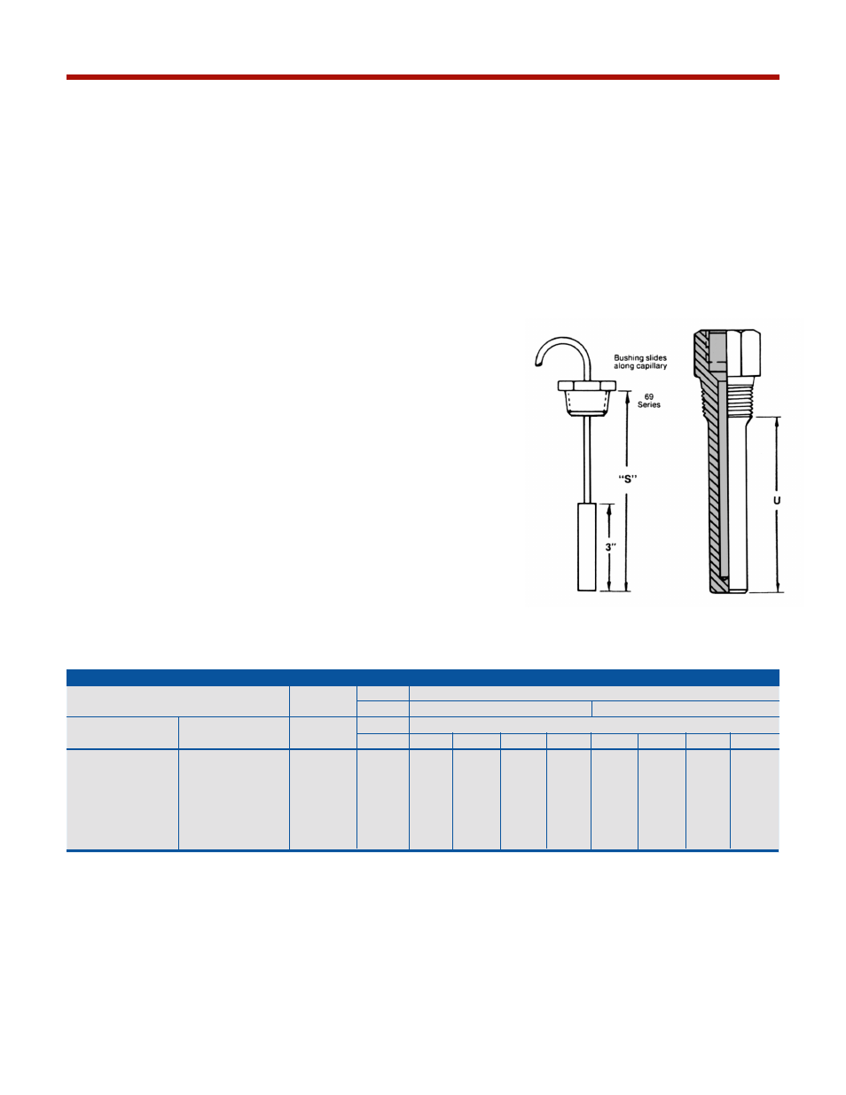
Thermowell bushings should be
used with remote mount tempera-
ture switches. We recommend the
standard 3˝ bulb and code 69
Series bushings for use with any
thermowell “U” dimension. A split
rubber grommet allows easy
installation and “S” dimension
adjustment.
G and L TEMPERATURE SWITCHES
5. Not available with 2
3
/
4
”stem
6. Available with remote mount thermal system only.