Operation – Ryobi A25RE02 User Manual
Page 5
4
5
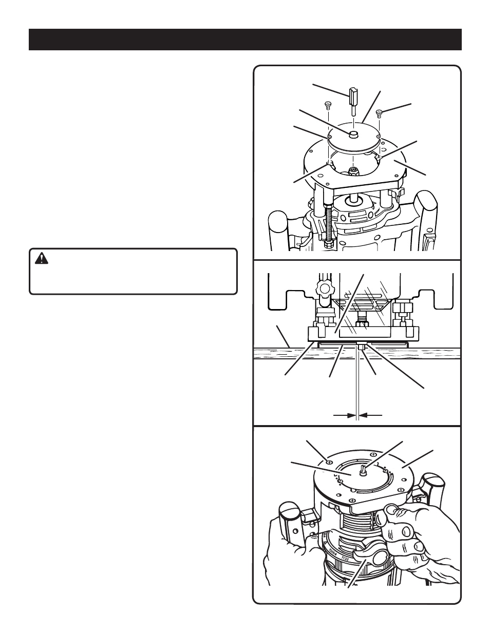
Fig. 5
Fig. 6
WORKPIECE
CUTOUTS
ROUTER BASE
TEMPLATE GUIDE
BUSHING COLLAR
ROUTER
BIT
SUBBASE
SIZE DIFFERENCE
ROUTER
BIT
COLLAR
SUBBASE
RECESS IN
BASE
SCREW
TEMPLATE GUIDE
BUSHING
HOLES
IN BASE
OPERATION
ROUTING WITH GUIDE BUSHING
You can accurately duplicate curves and complex shapes by
fitting your router with a template guide bushing that extends
below the subbase. The router bit passes through the guide
bushing. The guide bushing then rides against a template.
INSTALLING TEMPLATE GUIDE BUSHING
See Figures 5 - 7.
n
�
Unplug your router.
n
�
Place router upside down on workbench.
n
�
Place template guide bushing in recessed portion of
router base.
n
�
Align the cutouts in guide bushing with threaded holes in
base.
n
�
Secure guide bushing to router base with screws pro-
vided.
n
�
Tighten screws securely.
WARNING:
Failure to tighten screws could cause bit to come in con-
tact with bushing, resulting in serious injury.
When routing with template guide bushings it is necessary
to allow for size differences between the cutting edge of the
bit and the face of the guide bushing collar. When making
templates, always allow for this size difference.
NOTE: Special Instructions for use with routers R181D,
R181FB, R181PF, R1801M, and RE1802M.
n
Unplug your router.
n
Follow the previous steps to secure the guide bushing to
subbase.
n
Tighten screws securely.
n
Loosen the 4 subbase screws that secure the subbase
to the router base.
n
Set bit to desired depth and lock depth lock.
n
Adjust subbase so that the end of the bit is centered in
collar of the bushing.
n
Tighten the 4 subbase screws securely.
Fig. 7
SUBBASE SCREW
BIT
SUBBASE
TEMPLATE
GUIDE
BUSHING
DEPTH LOCK LEVER
TEMPLATE
GUIDE