Assembly – Ryobi A25RE02 User Manual
Page 3
2
3
UNPACKING
This product requires assembly.
n
Carefully remove accessories from the box. Make sure
that all items listed in the packing list are included.
n
Inspect the accessories carefully to make sure no break-
age or damage occurred during shipping.
n
Do not discard the packing material until you have care-
fully inspected and satisfactorily operated the tool.
n
If any parts are damaged or missing, please call
1-800-525-2579 for assistance.
PACKING LIST
Router Bit Set (15)
Router Lettering Template Set
2-1/2 in. Letter and Number Template Set
1-1/2 in. Letter and Number Template Set
Hardware for Mounting Letter Template Set
Guide Bushings (5) with Screws (2)
DVD
CD
Non-skid Mat
Tool Bag
Operator’s Manual
WARNING:
If any parts are missing do not operate this product until
the missing parts are replaced. Failure to do so could
result in possible serious personal injury.
WARNING:
Do not attempt to modify these accessories. Any such
alteration or modification is misuse and could result in a
hazardous condition leading to possible serious personal
injury.
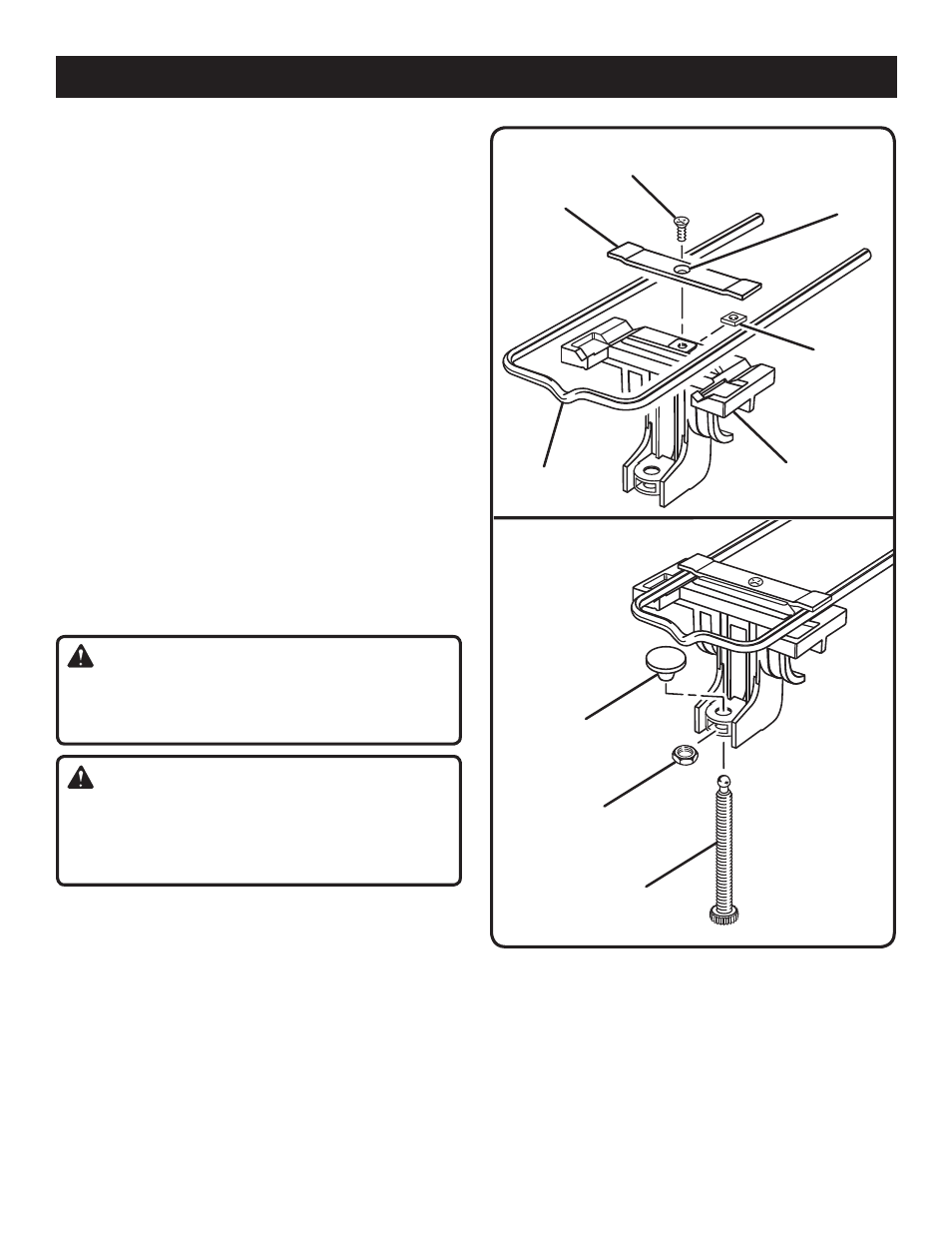
ASSEMBLING THE U-BOLT, MOUNTING
BRACKET, AND CLAMP SCREW
See Figures 1 - 2.
n
Lay the U-bolt clamp on the mounting bracket with the
countersink up, away from the mounting bracket.
n
Fit the square nut under the bracket and insert the flat
head screw in the countersink.
n
Slide the U-bolt under the clamp and tighten the flat head
screw.
MOUNTING BRACKET
ASSEMBLY
Fig. 1
Fig. 2
HEX NUT
U-BOLT
FLAT HEAD
SCREW
SQUARE
NUT
U-BOLT CLAMP
SWIVEL
BUTTON
CLAMP SCREW
COUNTERSINK
n
Insert the hex nut into the slot located in the lower part
of the mounting bracket.
n
Thread the clamp screw through the nut with the ball end
pointing up.
n
Push the swivel button on the ball end of the clamp
screw.