Prepare the receiver collar, Step, Readytest – Petsafe UltraSmart® In-Ground Fence™ User Manual
Page 13: Feature
www.petsafe.net 13
6. Insert the ends of the twisted transmitter wires into the right 2 black connectors
at the bottom of the Surge Protector labeled “Transmitter”.
7. Pull the tab on the Fence Transmitter to the left to insert the opposite ends of
the twisted wire into the Loop Wire Terminals.
8. Turn the Field Width Control knob to the 9 o’clock position.
9. Plug in the Transmitter power adapter to the outlet on the front of the Surge
Protector and turn the Fence Transmitter ON.
10. The Indicator Light on the Transmitter should illuminate to green indicating
a properly installed boundary loop. If this does not happen, refer to the
Transmitter Status Indications label underneath the Transmitter lid (6C) or see
the “Troubleshooting” section in this guide.
For added protection, when unused for long periods of time or prior to
thunderstorms, unplug from the wall outlet and disconnect the Loop
Boundary Wires. This will prevent damage to the Transmitter due to surges.
Indicator Light
6C
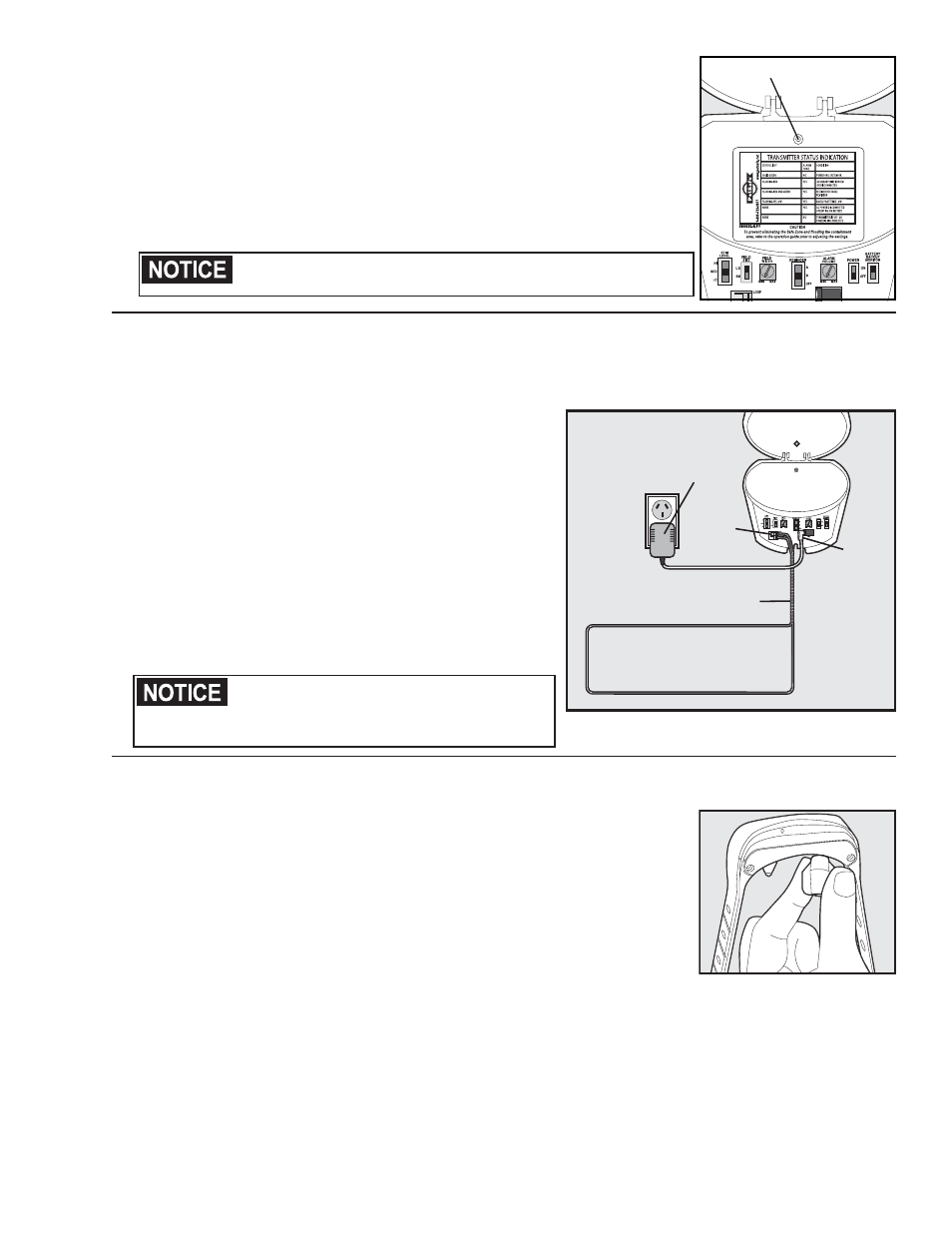
Connect the Wires to the Fence Transmitter
(Australia & New Zealand)
1. Run the Boundary Wire through a window, under a door,
through a crawl space vent, or any other appropriate available
access. You can also drill a hole through your wall.
2. Strip
3
⁄
8
inch of insulation from the ends of the Boundary
Wire.
3. Pull the tab on the Fence Transmitter to the left to insert the
Boundary Wire into the Loop Wire Terminals.
4. Turn the Field Width Control knob to the 9 o’clock position.
5. Plug in the transmitter power adapter into the Power Jack and
AC power outlet and turn the Fence Transmitter ON.
6. The Indicator Light on the transmitter should illuminate to
green indicating a properly installed boundary loop. If this
does not happen, refer to the Transmitter Status Indications
label underneath the transmitter lid (6C) or see the
“Troubleshooting” section in this guide.
For added protection, when unused for long
periods of time or prior to thunderstorms, unplug
from the wall outlet and disconnect the Loop
Boundary Wires. This will prevent damage to the
Transmitter due to surges.
Power
Adapter
Boundary Wires
(Twisted)
Loop
Wire
Terminals
Boundary Wire
Loop
Power
Jack
6D
Prepare the Receiver Collar
Your Receiver Collar comes with short Contact Points installed. Use the long Contact
Points for pets with long or thick hair. Tighten the Contact Points using the Contact
Point Wrench (7A). Check the tightness weekly.
ReadyTest
®
Feature
ReadyTest
®
gives you added confidence that the Receiver Collar is working and
ready to use. When you remove the Receiver Collar from the charger, the receiver
will automatically go into self-test mode for approximately 8 seconds. The receiver’s
internal diagnostics will check that the battery charge is full and that all circuits are
working correctly. Do not touch the Contact Points while
7A
the receiver is in test mode. When the collar is removed from the charger, the indicator light will go off and then
come back on. The light will first glow red for three seconds, then go off. The indicator light will come back on for
five seconds to indicate the status of the battery (green, yellow or red). The ReadyTest
™
is complete once you see
the battery indicator status.
If the Receiver Collar beeps and the indicator light glows solid red for 20 seconds, the ReadyTest
®
self-test has
failed. Replace the Receiver Collar in the charger for 5 seconds and then remove. Do not touch the Contact Points.
If the Receiver Collar continues to fail the ReadyTest
®
, call the Customer Care Center.
Step
7