Petsafe Innotek Basic In-Ground Fence User Manual
Page 12
TROUBLESHOOTING GUIDELINES
A. Dog is not responding to correction:
• Adjust the collar fit.
• Trim the dog’s hair or use longer probes to make better skin contact.
• Change and/or recharge the battery in the collar receiver.
• Be sure the wall transmitter jumper is set at 8.192 kHz. (Battery-operated receiver system only).
For more information, visit our web site at www.innotek.net.
NOTE FOR RECHARGEABLE SYSTEMS ONLY:
If your dog is not responding to the correction, the recharge-
able
system has the option of setting the correction level on the
wall transmitter for Low, Medium, or High. The factory set-
ting is
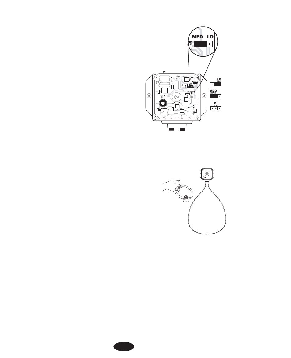
Medium. If you want to change the level:
1. Turn the Field Width knob to the “off” position. Remove
the
knob, the four cover screws and the front cover.
2. The jumper in the upper right corner of the transmitter can
be moved to the right for the Low setting or completely
removed for the High setting.
3. Replace the transmitter cover and the four cover screws
4. Install the knob with the pointer to the “off” position.
5. Retest the signal field width as described in Step 10.
NOTE: If the transmitter is set on High, there will be
no pre-correction warning tone.
B. System Test Procedure:
Whenever you experience a malfunction, you will need to do a Test
Loop to determine which component - collar, wall transmitter, or
yard wire - is not working. To perform the Test Loop procedure:
1. Make a test loop using a piece of wire at least 4 meters in length.
2. Remove the existing wire from your wall transmitter.
3. Insert the two ends of the test loop wire into the wall transmitter.
4. Turn the field width knob to the 9 o’clock position or a low setting.
5. Place the test light on the collar receiver. With the collar in hand,
move outside the field and approach the test loop. Make a mental
note of the distance between the collar and the wire when the collar
activates.
6. Turn the field width knob to 12 o’clock or a medium setting.
7. Back away from the wire and approach it again. Determine the
distance between the collar and the wire when the collar activates.
The distance should be greater on the medium range setting.
8. If more than one collar receiver is used with the system, repeat the above test on each collar.
INDICATOR LIGHT
Field
Width
SMART DOG
12