Fig 5 – PDR Mounts awm175 User Manual
Page 8
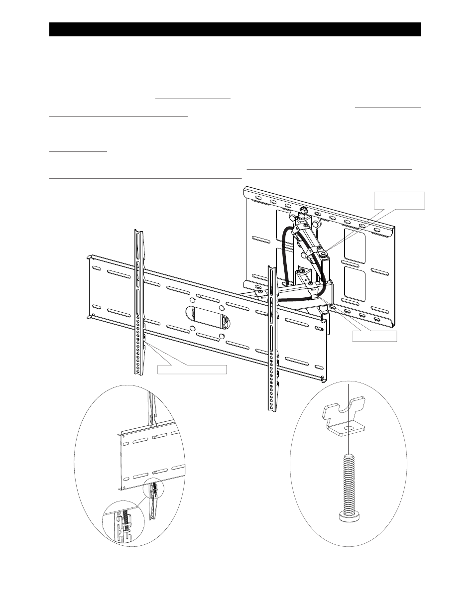
3. TYPICAL PDR PANEL MOUNTING TO ARTICULATING ARM, TENSION CONTROL AND CABLE MANAGEMENT
The display height can be set by using any of the three position slots on the display bracket (A)
Locking tabs are supplied (
20 and 39) in the AWM175 kit .
Assemble the locking tab kit PDM-0066 (items
20 & 39) and insert into the slot in the display arm. (See Fig 5 & 5a)
Center the display on the mounting bracket (B) and tighten the screws (
39) on the locking tab (20). Care should be taken not to over
tighten screws (39).
Determine which way the mount will close before attaching the cable management brackets.
Attach the cable brackets (
27) on the top and middle tube only using the self tapping screws (26) supplied. If the self taping screws (26)
are used for the cable brackets (
27) and the screw lock tab (16), remember to install the screw lock tab (16). Failure to do so could
allow the long shaft (12) to loosen and fall out . Check cable position to make sure cable is not pinched when the mount is opened
and closed.
If needed, use adjustment knob (
31) to adjust the up and down tilt. Secure the displays up and down tilt feature using the plastic tri knobs
(35).
Adjusting tension: The tension bolt adjustments are required to keep the display from creeping from the desired location. Loosen the
screw (26) and lift the screw lock tab (
16) and swing to the side. Using two 7/16 wrenches, tighten the screws (17) until enough tension
is applied to keep the display from creeping from the desired location.
Make sure to replace the screw lock tab (16). Failure to
replace could result in the screw (17)and shaft (12) backing out. Tighten the tension bolts (17) to suit the weight of the display.
8
Fig 5
Height adjust slots
Fig 5a
Tension bolt &
screw lock tab
Cable Hanger
View from the back side of the AWM175
with locking tab in place