Installation – Nexen XHW 848200 User Manual
Page 5
5
FORM NO. L-20004-K-1209
INSTALLATION
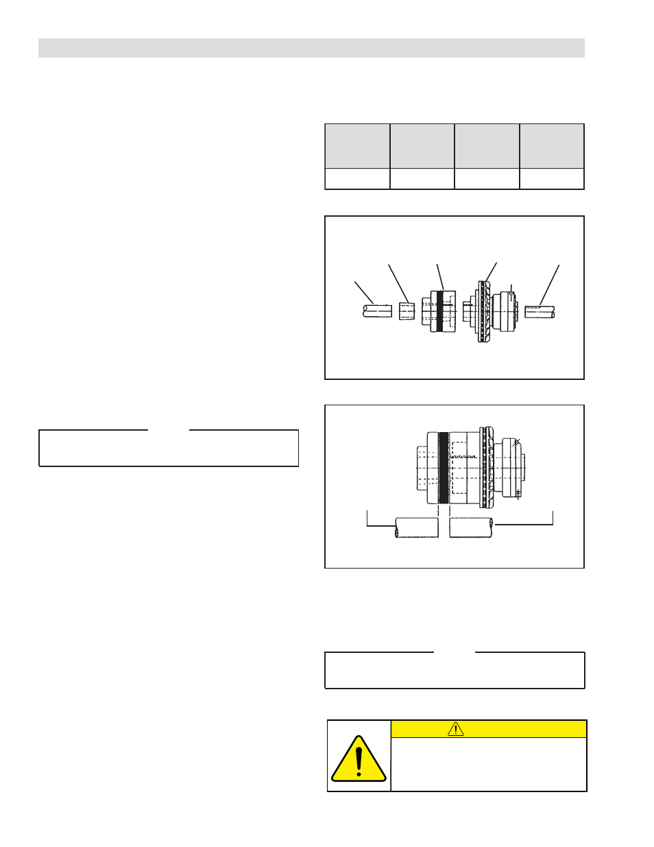
Refer to Figures 1 & 2.
SHEAVE MOUNT AND PILOT MOUNT
1. Insert Key (Item #21) into shaft keyway.
2. Slide clutch onto shaft, fully seating Key (Item #21)
into Hub (Item #1).
3. Align sheaves and belts.
4. Tighten Set Screws (Item #17 and #28) to 12 ft. lbs.
torque.
COUPLING MOUNT
Consists of Pilot Mount Clutch and Coupling Half. Use
Dodge Taper-lock bushing #3030 in Coupling Half.
1. Determine the parallel misalignment of the shafts to be
coupled. Place a straightedge across the shafts and
measure the maximum offset at various points around
the periphery of the shafts.
2. Make necessary corrections to keep within the parallel
misalignment limits of the clutch coupling.
NOTE
Fix the driving shaft and allow the driven shaft to float.
Refer to Table 1 for max. misalignment values.
3. Attach Coupling Adapter Plate Assembly (Item #22)
to the clutch, using Cap Screws (Item #31) and Lock
washer (Item #32).
4. Slide clutch assembly onto the driving shaft until end
of clutch is flush with the shaft end.
5. Insert Key (Item #21) into driving shaft key way.
6. Tighten Set Screws (Item #17 and #23) to 12 ft. lbs.
torque.
7. Place the coupling’s Flexible Disc (Item #23) over the
coupling’s adapter plate pins.
8. Insert Dodge Taper-lock bushing (customer supplied)
into coupling half.
9. Align the hole (not threads) and slide Taper-lock bushing
assembly onto the driven shaft until bushing end is flush
with the shaft end.
10. Thread screws into the threaded holes in the coupling
and tighten alternately and evenly.
Driven
Shaft
Taper
Lock
Bushing
Coupling
Half
Pilot Mount
Unit
Driving
Shaft
FIGURE 1
Driven
Shaft
Driving
Shaft
FIGURE 2
11. Align the pins in the Coupling Flange (Item #24) with
the holes in the flexible disc.
12. Push entire assembly together.
NOTE
Automatic spacing is accomplished by spacers molded
into the flexible coupling.
13. Secure the driven shaft.
R
A
L
U
G
N
A
-
N
G
I
L
A
S
I
M
T
N
E
M
L
E
L
L
A
R
A
P
-
N
G
I
L
A
S
I
M
T
N
E
M
G
N
I
V
I
R
D
T
F
A
H
S
N
O
I
T
R
E
S
N
I
N
E
V
I
R
D
T
F
A
H
S
N
O
I
T
R
E
S
N
I
0
5
1
.
5
1
0
.
5
2
.
0
1
0
.
3
TABLE 1
CAUTION
This unit has rotating parts. Provide a guard
that will not restrict the flow of cooling air
around the unit when installed in an area
where injury to an operation could occur.