Installation – Nexen I300 965502 User Manual
Page 4
FORM NO. L-21226-B-1008
4
INSTALLATION
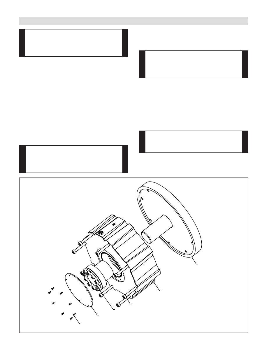
Refer to figure 1 for the following steps.
1. Remove cover (Item 7) by removing the 8 cap
screws (Item 11) before installation
2. Mount brake to machine bulkhead using 8 customer
supplied M8 cap screws***, the outside diameter of
the brake should be used as a pilot to ensure proper
alignment with the machine shaft.
*** Each end of the brake’s mounting holes is
threaded with M10 X 1.25 threads to depth
20.0 (.79 in); the brake may be mounted using
these threaded holes if it is a better fit for a given
application.
Danger
Ensure all loads are supported before installing
brake. Failure to support the load could result in
serious bodily injury.
Important
The locking collar used for mounting must be a
non-translating type. If the wrong type of collar
is used, damage to the brake will occur.
Important
The mounting edge of this brake is not sealed,
if using the brake in a wet environment ensure a
flange sealant is used to keep water from
entering the brake.
3. Install the customer supplied locking collar into
brake, do not lubricate either the clamping collar or
shaft, do not tighten collar at this point.
MACHINE BULKHEAD
MOUNTING SCREWS
*CUSTOMER SUPPLIED COLLAR*
ITEM 7
ITEM 11
I300
Figure 1
4. With the brake mounted rigidly to the customer’s
bulkhead and the brake in the ENGAGED position,
tighten the cap screws on the collar to the
manufactures recommended torque.
5. Apply sealant (silicone or RTV) to o-ring before
installing the cap. Install the cap (item 7) using the
8 cap screws (Item 11).
Danger
Brake housing has sharp corners,
guard brake as required.