Nexen RPS16G-C0070T/360-EP2U 966554 User Manual
Page 13
13
FORM NO. L-21252-B-1209
APPLYING PRELOAD
If you would prefer to not design your own pinion
preloading mechanism, Nexen offers a high precision push
bolt preloading system that bolts between the machine
frame and servo reducer to simplify machine design and
achieve optimal results. See figure 17.
Preloading Procedure
Note: Be careful engaging the pinion and servo as-
sembly to the gear to avoid damaging the gear
teeth or pinion rollers.
1. With a dial indicator mounted on the movable carriage,
measure off the tooth peaks. Move the carriage down
the run taking frequent measurements to locate the
high spot in the run. This is where the pinion preload-
ing should be done to prevent excessive preload from
occurring elsewhere in the run.
2. Apply serviceable thread locking compound to the
pinion preloader slider bolts and install the servo and
preload mechanism. Ensure the preload related bolts
are just loose enough to allow the pinion to be pulled
away from the gear teeth. For the Nexen Preloader
System, this is approximately 0.2 - 0.3 Nm [2 - 3 in-
lbs].
Nexen Precision Pinion Preloader product numbers and
more information can be found at www.nexengroup.com
on any of the RPG pinion pages under accessories in the
left hand column.
To ensure optimal meshing of the roller pins with the
gear teeth, the shaft must be preloaded to 0.010 - 0.015
mm [0.0004 - 0.0006 in] beyond full roller/tooth root
engagement.
Figure 17
NOTE: Do not apply excessive preload. Preloading
beyond 0.015 mm [0.0006 in] will decrease product
life, increase noise, and cause vibration. When the
RPG system is properly preloaded, there will be no
tangential play between the gear teeth and the pinion
rollers if the pinion is not allowed to turn and the
rotating assembly forced back and forth in the direction
of rotation.
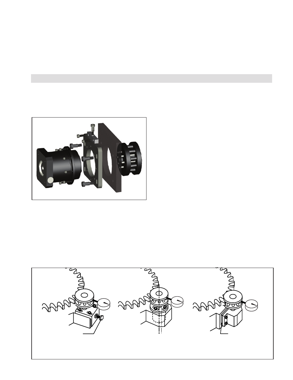
Refer to Figure 18 for suggested preload methods.
17. Re-torque the mounting screws once more to the full-
specified torque value in Table 4 to ensure full torque
has been reached on all fasteners. Tighten in the same
order as above.
18. Repeat variance inspection Step 15 and verify the
variance listed is achieved after fully torquing the
pinion. If variance is out of specifications the pinion
should be removed inspecting for contaminates, burs,
or surface defects that would interfere with full contact
between the adapter (if used) and gearhead flange.
Indexing the pinion relative to the adapter (if used) or
gearhead may help in some cases. Repeat the pinion
installation procedure starting with Step 13.
Push Bolt
Figure 18
Adjustment by Oblong Holes
(Preferred Method)
Adjustment by Eccentric Holes
(Option 1)
Adjustment by Shim
(Option 2)
Shim
- RPS25G-C0075T/360-EP2U 966564 RPS16G-C0060T/360-EP2U 966553 RPS25G-C0060T/360-EP2U 966563 RPS32G-B0760T/009-EP2U 966778 RPS16G-C0050T/360-EP2U 966552 RPS25G-C0050T/360-EP2U 966562 RPS16G-C0040T/360-EP2U 966551 RPS25G-C0040T/360-EP2U 966561 RPS40G-B0048T/360-EP2U 966764 RPS32G-B0048T/360-EP2U 966636 RPS25G-C0030T/360-EP2U 966560 RPS16G-C0030T/360-EP2U 966550 RPS32G-B0450T/14.4-EP2U 966763 RPS40G-B0200T/020-EP2U 966549 RPS20G-C0150T/060-IP2U 966614 RPS16G-C0936T/010-EP2U 966555 RPS25G-C0486T/020-EP2U 966739 RPS4014G-B0072T/090-EP2U 966696 RPS16G-C0400T/023-EP2U 966655 RPS20G-C0180T/060-EP2U 966733 RPS16G-C0150T/091-EP2U 966657 RPS16G-C0150T/072-EP2U 966667 RPS20G-C0140T/072-EP2U 966705 RPS4014G-B0192T/023-EP2U 966725