Nexen RPS16G-C0070T/360-EP2U 966554 User Manual
Page 11
11
FORM NO. L-21252-B-1209
Table 3
Pinion Bushing Bolt Information
Model
Bolt Type
Tightening Torque
RPG16
M4
3.5 Nm [30.98 in-lb]
RPG20
M5
7.0 Nm [61.96 in-lb]
RPG25
M6
12.0 Nm [106.21 in-lb]
RPG32
M6
12.0 Nm [106.21 in-lb]
RPG40
M6
12.0 Nm [106.21 in-lb]
RPG4014
M8
38.0 Nm [336.26 in-lb]
Flange Mount Pinion Installation (ISO 9409)
1. Clean the gearhead mounting face and pilot bore,
inspecting for contaminates, burs, or surface defects
that would interfere with full contact between the
pinion and flange.
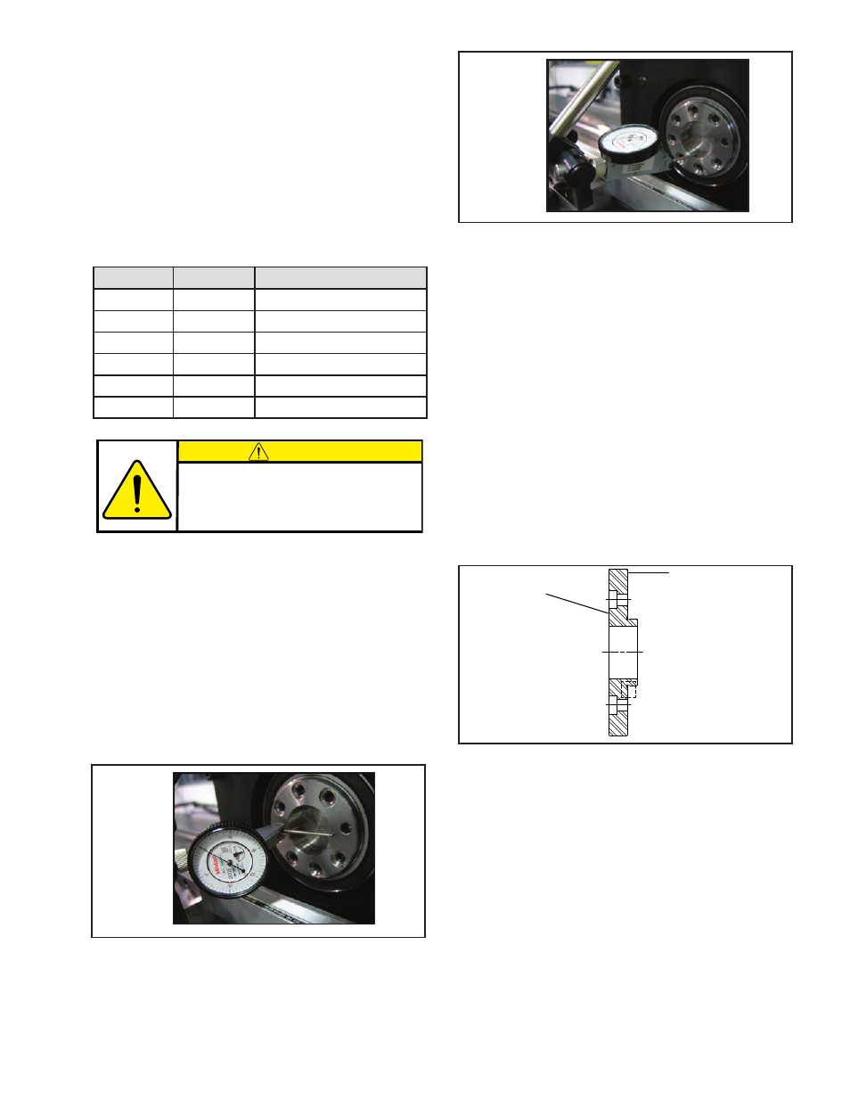
2. Using a test indicator, check the rotational flatness of
the face as shown in Figure 12. Position the contact
point of the indicator where the pinion will contact
it. Rotate slowly for a minimum of one complete
revolution and note the total amount of variance.
Pinion Side
Gearhead Side
Figure 14
3. Position the contact point of the indicator at bottom
dead center of the pilot bore as shown in Figure 13.
Rotate slowly for a minimum of one complete turn and
note the amount of total variance in one rotation.
10. Once the fasteners are fully torqued verify the pinion
is centered on the gear. If not, measure the positional
error and then remove the pinion as described in the
Disengaging The Roller Pinion section on page 16.
Repeat the pinion installation procedure and offset the
pinion by the recorded error plus the previous off set
value. When the pinion is fully torqued and properly
centered then verify pinion concentric variation at the
center of the pinion rollers as shown in Figure 15.
Variation on this surface must be less than ± 0.030
mm [±0.0010 in].
4. If either of the following conditions are true, the
gearhead itself may contribute to excessive pinion
preload variation, a reduction in pinion life and/or
accuracy. The user should consider having the
gearhead re-worked or replaced.
a. The measured total variance of the mounting face is
greater than 0.013 mm [0.0005 in].
b. The measured total variance of the pilot bore wall is
greater than 0.005 mm [0.0002 in].
Note: In some cases an adapter will be required to mount
the pinion on the reducer. If so, proceed with Step
5, if not, skip to Step 13.
5. Clean the adapter flange and pilot where it will contact
the gearhead flange inspecting for contaminates,
burs, or surface defects that would interfere with full
contact between the adapter and gearhead flange.
See Figure 14.
6. Apply a serviceable thread locking compound to the
adapter mounting screws then assemble the adapter
to the gearhead, leaving the mounting screws snug but
do not tighten at this time as shown in Figure 15.
7. Position a test indicator at bottom dead center of
the pilot bore wall as shown in Figure 15 and zero
the indicator. Rotate the assembly slowly by using
the gearhead input shaft a minimum of one complete
revolution while noting the amount of total indicator
variance and mark the angular location in which the
lowest reading occurs throughout the rotation.
.
Figure 12
Figure 13
CAUTION
Preload must be applied before putting your
system into operation. Refer to APPLYING
PRELOAD to properly set preload for your
RPG system.
- RPS25G-C0075T/360-EP2U 966564 RPS16G-C0060T/360-EP2U 966553 RPS25G-C0060T/360-EP2U 966563 RPS32G-B0760T/009-EP2U 966778 RPS16G-C0050T/360-EP2U 966552 RPS25G-C0050T/360-EP2U 966562 RPS16G-C0040T/360-EP2U 966551 RPS25G-C0040T/360-EP2U 966561 RPS40G-B0048T/360-EP2U 966764 RPS32G-B0048T/360-EP2U 966636 RPS25G-C0030T/360-EP2U 966560 RPS16G-C0030T/360-EP2U 966550 RPS32G-B0450T/14.4-EP2U 966763 RPS40G-B0200T/020-EP2U 966549 RPS20G-C0150T/060-IP2U 966614 RPS16G-C0936T/010-EP2U 966555 RPS25G-C0486T/020-EP2U 966739 RPS4014G-B0072T/090-EP2U 966696 RPS16G-C0400T/023-EP2U 966655 RPS20G-C0180T/060-EP2U 966733 RPS16G-C0150T/091-EP2U 966657 RPS16G-C0150T/072-EP2U 966667 RPS20G-C0140T/072-EP2U 966705 RPS4014G-B0192T/023-EP2U 966725