Caution, Danger – Metalfab Motorized Trolley MR Series User Manual
Page 20
20
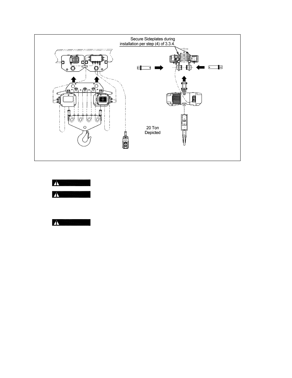
Figure 3-11
Optional trolley installation method – 8 Ton and Larger
3.4 Electrical
Connections
3.4.1
CAUTION
Ensure that the voltage of the electric power supply is proper for the hoist or trolley.
3.4.2
CAUTION
Do NOT apply electronic soft-start control or voltage varying controls to the MR
trolley. Use of such devices may cause the motor brake and other electrical components to
malfunction. Variable frequency drives MAY be used with MR trolleys, contact Harrington for more
information.
3.4.3
DANGER
Before proceeding, ensure that the electrical supply for the hoist or trolley has
been de-energized (disconnected). Lock out and tag out in accordance with ANSI Z244.1 “Personnel
Protection -Lockout/Tagout of Energy Sources”.
3.4.4
This instruction applies to installations where an ER or NER model electric hoist is installed on an MR
trolley. In this case the hoist and trolley are controlled by a pendant with four push buttons – two for the
hoist motion and two for the trolley motion. Special wiring considerations must be taken if the trolley is
used with a hoist other than an ER or NER model.
Pendant Cord - The Pendant Cord connects to the trolley via an 8-pin (8P) Plug and Socket. Make
this connection as follows:
1)
Refer to
Figure 3-12 or 3-13
depending on the product code of the trolley/hoist.
2)
Insert the 8P Plug into the 8P Socket on the Switch Box and hand tighten the Screw Coupling.
3)
For trolley/hoist code ERM001H to ERM100L – Install the Cord Strain Relief Cable to the Cord
Support on the Bar Holder.
4)
For trolley/hoist code ERM100S – install the Cord Strain Relief Cable onto Cord Strain Relief
Stopper located at the 8P socket.
5)
For trolley/hoist code ERM150S and ERM200S – Install the Cord Strain Relief Cable onto
Connection Plate S.