Internet version for reference only – Bradford White TW4-75S-76B-3X User Manual
Page 18
18
Installation (Venting (Part I)) continued-
Part II - Venting Specifications for:
40 Gallon, 40,000 BTU input (151.4 L, 11.7 kW/Hr)
48 Gallon, 40,000 BTU input (189.3 L, 11.7 kW/Hr)
This water heater is a power vented appliance and is designed to vent its
products of combustion through 2” (5.1 cm) or 3” (7.6 cm) diameter Schedule
40 (solid or cellular core) PVC pipe to the outdoors. The water heater may be
either vented through the wall or vertically through the roof. Use a 3” (7.6 cm)
to 2” (5.1 cm) reducer to connect to the vent outlet when using 3” (7.6 cm)
PVC. Apply PVC cement at PVC locations. Table 7 lists the maximum vent
lengths for this water heater using 2” (5.1 cm) PVC. If possible, locate the
water heater so that the venting length and number of elbows are kept to the
minimum distance necessary to reach the outside. If the installation requires
venting lengths that exceed the lengths listed for 2” (5.1 cm) PVC in Table 7
then use 3” (7.6 cm) PVC for the vent connector. Table 8 lists the venting
distances allowed with 3” (7.6 cm) diameter PVC pipe. When venting with 3”
(7.6 cm) PVC, use a 3” (7.6 cm) to 2” (5.1 cm) reducer to exit through the
building wall with 2” (5.1 cm) PVC. Use the 2” (5.1 cm) vent terminal supplied
with the water heater to terminate on the outside of the building. If the length of
the 2” (5.1 cm) needed to go through the wall is greater than 14” (35.6 cm), use
3” (7.6 cm) PVC to go through the wall and reduce to 2” (5.1 cm) PVC
immediately after exiting the outside wall. Refer to the venting illustrations on
the following pages. Make sure the vent pipe terminal is at least 1” (2.5 cm)
away from the edge of the wall. To vent horizontally with zero (0) elbows,
remove 3 screws from blower housing and rotate the blower housing 90°
clockwise (see Figure 7). Replace the three (3) screws once blower
housing rotation is complete.
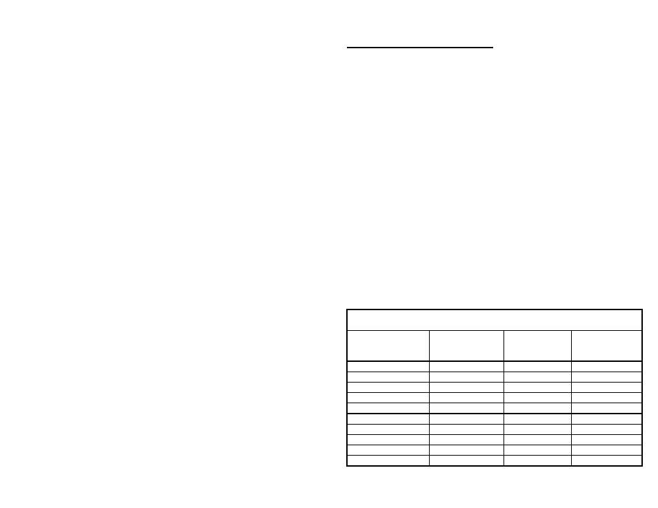
TABLE 7- VENT CONNECTOR LENGTHS FOR 2” (5.1cm) DIAMETER
PVC
Terminating
# of 90
° Elbows
(excluding vent
terminal)
Maximum
Length
Minimum
Length
Through the Wall
0
45 ft (13.7m) 2
ft
(.6 m)
Through the Wall
1
40 ft (12.2m) 2
ft
(.6 m)
Through the Wall
2
35 ft (10.7m) 2
ft
(.6 m)
Through the Wall
3
30 ft (9.2 m) 2
ft
(.6 m)
Through the Wall
4
25 ft (7.6 m) 3
ft
(.9 m)
Through the Roof
0
31 ft (9.5 m) 3
ft
(.9 m)
Through the Roof
1
28 ft (8.5 m) 3
ft
(.9 m)
Through the Roof
2
25 ft (7.6 m) 3
ft
(.9 m)
Through the Roof
3
22 ft (6.7 m) 3
ft
(.9 m)
Through the Roof
4
19 ft (5.8 m) 4
ft
(1.2 m)
Internet Version for Reference Only