Internet version for reference only – Bradford White TW4-75S-76B-3X User Manual
Page 13
13
Installation (Venting (Part I)) continued-
TABLE 3 -VENT CONNECTOR LENGTHS
FOR 4” (10.1 cm) DIAMETER PVC
Terminating
# of 90
° Elbows
(excluding vent
terminal)
Maximum
Length
Minimum
Length
Through the Wall
1
70 ft (21.3 m) 2
ft
(.6 m)
Through the Wall
2
65 ft (19.8 m) 3
ft
(.9 m)
Through the Wall
3
60 ft (18.3 m) 5
ft
(1.5 m)
Through the Wall
4
55 ft (16.8 m) 8
ft
(2.4 m)
Through the Wall
5
50 ft (15.3 m) 12
ft
(3.6 m)
Through the Roof
1
70 ft (21.3 m) 2
ft
(.6 m)
Through the Roof
2
65 ft (19.8 m) 3
ft
(.9 m)
Through the Roof
3
60 ft (18.3 m) 5
ft
(1.5 m)
Through the Roof
4
55 ft (16.8 m) 8
ft
(2.4 m)
Through the Roof
5
50 ft (15.3 m) 12
ft
(3.6 m)
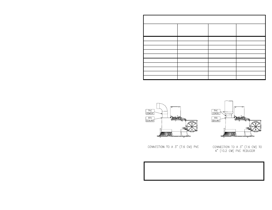
NOTE: When using 4” (10.1 cm) PVC, use a 4” (10.1 cm) to 3” (7.6 cm)
reducer and exit the building wall with 3” (7.6 cm) PVC using the 3” (7.6
cm) 90
° vent terminal supplied. Two 45° elbows are equivalent to one 90°
elbow.
Figure 2
NOTE: ABS or CPVC pipes may be substituted for PVC pipe. Do not mix
ABS and PVC pipe in the same installation.
IMPORTANT
All of the Venting connections must be leak checked with a soap and
water solution upon initial start up of the water heater. Any leaks must
be repaired before continuing operation of the water heater.
Internet Version for Reference Only