Defender, The bradford white, Safety system – Bradford White 65T-65FB-3X User Manual
Page 14
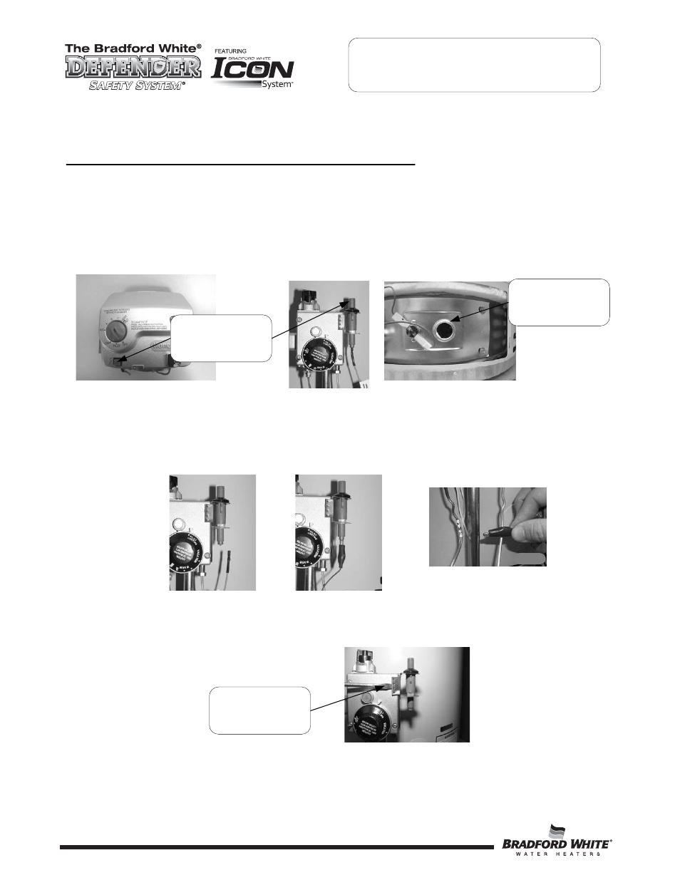
PIEZO IGNITER, ELECTRODE TESTING AND REPLACEMENT
With the pilot not in operation (no pilot flame) you can check the Piezo and electrode circuit by viewing pilot
thru the sight glass located on the inner door and observing the spark action.
Step 1.
Remove outer jacket door.
Step 2.
Repeatedly depress the Piezo igniter while viewing the pilot thru the sight glass. If a spark is
present, the circuit is OK. If there is no spark, proceed to step 3.
Step 3
Remove orange (or white) wire from Piezo igniter and install a jumper wire in its place. Hold the
other end of the jumper by the wire insulation or using an insulated tool, next to an unpainted
surface such as the feedline or gas valve and depress the Piezo igniter. If there is a spark, the igniter
is OK, the pilot is not functioning and must be replaced, see SERVICE PROCEDURE RG-III for
pilot replacement. If no spark is present the igniter is not functioning and must be replaced.
Step 4a.
For White Rodgers/Robertshaw gas valves: With orange wire disconnected from piezo igniter.
Using a common screw driver, place blade of screw driver under piezo bracket and gently pry
bracket from front of gas valve and unhook bracket from rear of gas valve.
View spark
Action through
Sight glass
Repeatedly
Depress Piezo
Igniter
Common Screw
Driver
The Bradford White
DEFENDER
Safety System
®
Step 4b.
For Honeywell gas controls: To replace igniter, see “Gas Control Disassembly/Reassembly” in
SERVICE PROCEDURE RG-VI.
SERVICE PROCEDURE RG-IV
Piezo Igniter, Electrode Testing
and Replacement
14
14
14
- 50T-65FB-3X 65T-65FB-3N 50T-65FB-3N M-2-XR65T6FSX M-2-XR504T6FSX M-1-XR403S6FSX M-4-60T6FSX M-4-5036FSX M-4-403S6FSX M-4-40T6FSX M-4-30T6FSX M-I-60T6FSX M-I-504S6FSX M-I-50L6FSX M-I-5036FSX M-I-404T6FSX M-I-403S6FSX M-I-40T6FSX M-I-30S6FSX M-I-303T6FSX M-I-30T6FSX M-2-XR65T6FBN M-2-XR504T6FBN M-1-XR403S6FBN M-4-60T6FBN M-4-5036FBN M-4-403S6FBN M-4-40T6FBN M-4-30T6FBN M-I-60T6FBN M-I-504S6FBN M-I-50L6FBN M-I-5036FBN M-I-404T6FBN M-I-403S6FBN