Blck, blcs, Installation, Specifications (cont’d.) – Chromalox PD411-10 User Manual
Page 4
FIRE HAZARD. An integral thermostat, if provided,
is designed for temperature control service only.
Because the thermostat does not fail safe, it should
not be used for temperature limiting duty. Wiring to
this device is the responsibility of the user.
The system designer is responsible for the safety
of this equipment and should install adequate
back-up controls and safety devices with their
electric heating equipment. Where the conse-
quences of failure could result in personal injury or
property damage, back-up controls are essential.
FIRE/EXPLOSION HAZARD.
Use only Explosion
Resistant Enclosures (E2, E3 or ER) in hazardous
atmospheres where flammable vapors, gases, liquids
or other combustible atmospheres are present as
defined in the National Electrical Code (NFPA 70).
Failure to comply could result in personal injury or
property damage.
ELECTRIC SHOCK HAZARD. Disconnect all power
before installing or servicing heater. Failure to do
so could result in personal injury or property dam-
age. Heater must be installed by a qualified person
in accordance with the National Electrical Code,
NFPA 70.
1. Before installing, check your Over-The-Side heater for any dam-
age that may have occurred during shipment. Also, check to ensure
that the line voltage is the same as that stamped on the nameplate.
2. Do not bend heating elements. If bending is necessary, consult factory.
3. IMPORTANT: Mount the heater in the tank so that the liquid
level will always be above the effective heated portion of the
heater. If the heater is not properly submerged, it will overheat and
damage the heating elements and create a possible fire hazard due
to excessive sheath temperatures. See “Warning” under
“Installation” section. (see Figure 3).
4. Heater must be supported from tank bottom. Heater must not be
operated in sludge. Sludge legs can be provided. Assemble as
shown in Figure 3.
5. Where work will pass over or near equipment, additional protec-
tion, such as a metal guard, may be needed.
6. In the electroplating operation the heaters are not, under any cir-
cumstance, to be placed between the electrodes and the work.
7. When melting solids by direct immersion, a surface vent should be
provided to allow gases to escape. Operate the heater on half volt-
age until melted material completely covers the heater area.
8. A drip loop is recommended to minimize passage of moisture
along wiring into terminal enclosure and connections.
FIRE HAZARD. Since heaters are capable of developing
high temperatures, extreme care should be taken to:
A. Use explosion-resistant terminal enclosures in hazardous loca-
tions. Consult Chromalox for selection of explosion-resistant
terminal enclosures for hazardous locations.
B. Avoid contact between heater and combustible materials.
C. Keep combustible materials far enough away to be free of the
effects of high temperatures.
FREEZE HAZARD. Some Over-The-Side heaters are
equipped with a thermowell for process control or
over-temperature control. Do not allow moisture to
accumulate in thermowell. Freezing temperatures
can cause damage that may result in the heated
medium leaking into terminal enclosure.
INSTALLATION
4
Specifications –
Kilowats
Dimensions (In.)
No.
Regular Oil
Fuel Oil
(A)
(B) Min. Tank
Model
Blades
Phase
18 W/in
2
12 W/in
2
40 W/in
2
Voltage
Riser Height Opening Clearance
(C)
BLCK-MH618
6
1 or 3
⌬
12
7.5
–
240 or 480
144
16-1/2
8-7/8
BLCK-MH824
8
1 or 3
⌬
16
10
–
240 or 480
144
16-1/2
12
BLCK-MH103
10
1 or 3
⌬
20
12.5
–
240 or 480
144
16-1/2
15-1/8
BLCK-MH236
12
1 or 3
⌬
24
15
–
240 or 480
144
16-1/2
18-1/4
BLCS-618
6
1 or 3
⌬
12
7.5
–
240 or 480
144
34
8-7/8
BLCS-824
8
1 or 3
⌬
16
10
–
240 or 480
144
34
12
BLCS-1030
10
1 or 3
⌬
20
12.5
–
240 or 480
144
34
15-1/8
BLCS-1236
12
1 or 3
⌬
24
15
–
240 or 480
144
34
18-1/4
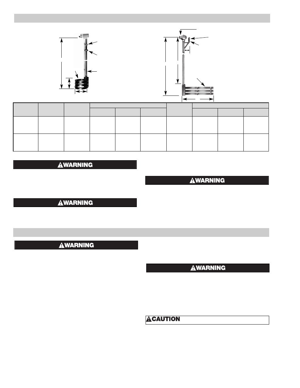
BLCK, BLCS
4 to 12 Blades
Type BLCK-MH
1-1/4” Ground Joint
Malleable Iron Union
1-1/4” Round
Floor Flange
Malleable Iron
1-1/4” Steel
Pipe Riser
Type BLCS
1-1/4” Pipe Opening
(4-5/32)
of Mtg. Hole
same as Dim. “A”
Suspension Bracket
4 to 12 Blades
CL
(C)
(B)
(A)
(A)
(C)
(B)
!
SPECIFICATIONS (cont’d.)