Cooling sequence of operation, 48e s -- a – Carrier 48ES---A User Manual
Page 22
22
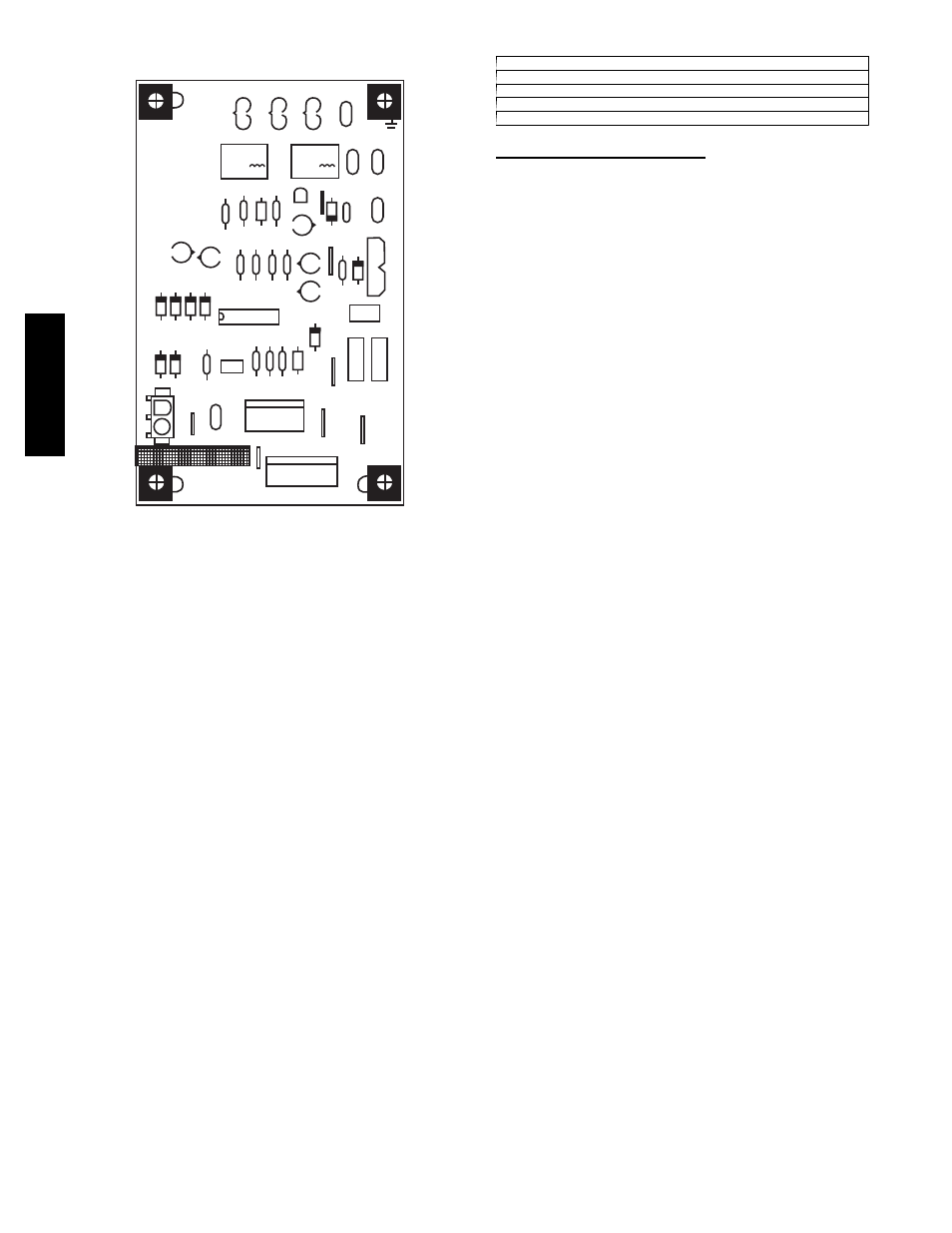
speed when the DH control lead is not energized, or IFB “HIGH”
speed when the DH lead is energized (see Fig. 18).
COM
LOW
HIGH
GAS
HEAT
Q1
R1L
C8
RL3
Q3
DCR
QCR
QC1
G1
G2
A7
D4
D6
C2
OILL
R9
AB A15
C4
C9
C0
R4
RL4
C7
R2
R3
R5 R6
QCB
Y
Y
R
U
C 24VAC
JW1
P2
P1
W2
Y2/
Y1/
Y
DH
G
C
R
SSTZ-8
P3
SDL
24V
AC/R
CDM/C
F1
QC6
QC7
QC4
QC3
K2
K1
D2
RI0
RI2
JM6
RI
DL
JM5
U1
C3
D3
D5
JW3
JW2
JW4
JW7
3 AMP
C
A09058
Fig. 18 -- Interface Fan Board (IFB)
Table 6 – Color Coding for Indoor Fan Motor Leads
Black = High Speed
Orange = Med--- High Speed
Red = Med Speed
Pink = Med--- Low Speed
Blue = Low Speed
Cooling Sequence of Operation
With the room thermostat SYSTEM switch in the COOL position
and the FAN switch in the AUTO position, the cooling sequence
of operation is as follows:
1. When the room temperature rises to a point that is slightly
above the cooling control setting of the thermostat, the
thermostat completes the circuit between thermostat
terminal R to terminals Y and G.
2. The normally open contacts of energized contactor (C) close
and complete the circuit through compressor motor
(COMP) to condenser (outdoor) fan motor (OFM). Both
motors start instantly.
3. The set of normally open contacts on the interface fan board
(IFB) are closed which energizes a circuit to the indoor fan
motor (IFM).
NOTE: Once the compressor has started and then stopped, it
should not be started again until 5 minutes have elapsed. The
cooling cycle remains on until the room temperature drops to a
point that is slightly below the cooling control setting of the room
thermostat. At this point, the thermostat breaks the circuit between
thermostat terminal R to terminals Y and G. These open circuits
deenergize contactor coil C. The condenser and compressor motors
stop. After a 90--sec. delay, the blower motor stops. The unit is in a
standby condition, waiting for the next call for cooling from the
room thermostat.
48E
S
--
A