Ab c – Workrite Series VALUE Assembly Instructions for Tables with Left Front Crank User Manual
Page 9
Workrite Ergonomics | 800.959.9675 www.workriteergo.com
9
Sonoma Series™ VALUE Workcenters - Assembly Instructions for Tables with Left Front Crank
a
b
c
11
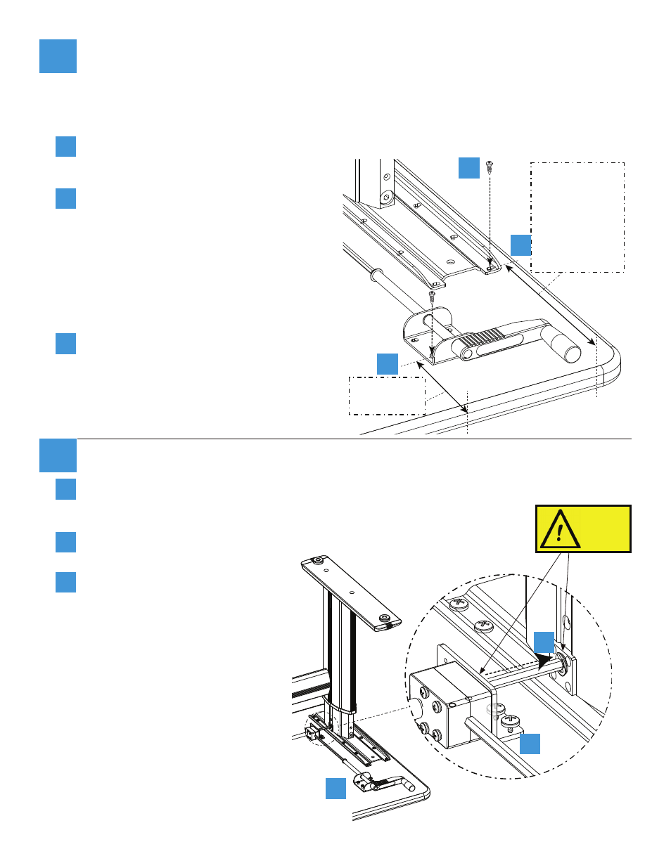
For Base-Only version: Secure Table Base to Tabletop
Position the leg assembly on the face-down table top. Center the assembly on the table so that
neither of the side legs overlap the edge. Mark the first two pilot holes to ensure that your table
will be positioned correctly as detailed below before drilling the remaining holes.
The front right mounting hole for the crank handle must be positioned precisely 4
⅞
" from the
absolute edge of the table as shown in the
diagram.
The front left mounting hole for Leg 1 must be
positioned precisely 10
⅞
" from the absolute
edge of the table as shown in the diagram if
you have a 30" base version, or 4
⅞
" from the
absolute edge of the table if you have a 24"
base version.
Be sure there is enough clearance in front of
the crank handle for crank rotation and hand
clearance.
Drill and insert screws for these two holes
first, then use the other screw holes to mark
the location of the remaining 28 holes. Attach
the desk at all points, but do not tighten the
screws that attach the crank handle at
this time.
4
⅞
" from
table edge to
mounting hole
10
⅞
" from table
edge to mounting
hole for 30" base
versions
or
4
⅞
" from table
edge to mounting
hole for 24" base
versions
a
b
c
V
V
a
b
c
12
Tighten Crank Handle to Desk
Push Crank Handle Assembly as close to leg
as possible, ensuring clips on hex rod are flush
against leg and gear box.
While pushing on crank assembly, tighten Wood
Screws connecting bracket to desk.
Tighten Wood Screws connecting
handle to desk.
Gear
box
a
b
c
Clips must
be flush
against the
leg and the
gearbox.