Tjernlund SS1C SideShot with UC1 Universal Control (Version X.04) 8504103 Rev C 02/04 User Manual
Page 22
21
DIAGRAM N
NOTE: Insufficient post-purge may cause limit to trip. If the limit switch trips, verify that the post-purge setting is long enough to
remove residual heat from the combustion chamber. If high limit trips repeatedly, do not operate the heater until the source of
excessive heat has been determined and repaired. If high limit will not reset and has an open circuit, replace high limit part num-
ber 950-0740. Verify inlet assembly sensing tube is clean. With SS1C running, verify that venter performance is sufficient to close
fan prover. Draft gauge should read a minimum of -0.04" w.c. at SS1C Prover sampling port. If draft gauge is unavailable, verify
that Venter performance is sufficient to close Fan Prover contacts by checking for continuity across switch. Replace Fan Prover
leads from P1 and P2 back on Fan Proving switch.
No, measured draft is less than -0.04" w.c.: Verify that SS1C vent hood draft adjustment is at proper setting, see “Draft
Adjustment Procedure”, page 17. Visually inspect system for blockages. Confirm that maximum BTU/hr. input and vent pipe
lengths are not exceeded. See “Application Table” on page 1 for capacities. Check fan proving switch sensing tube for blockage.
Yes, measured draft is at least -0.04" w.c.: Replace fan proving switch part number 950-0750.
MAINTENANCE
SERVICE TECHNICIAN AND USER REQUIREMENTS
1. SS1C must be visually inspected annually.
2. On oil, verify over-fire draft, CO
2
and smoke readings are all correct. See “Draft Adjustment Procedure” on pages 17, 18.
3. Annually inspect vent pipe for evidence of corrosion. If any corrosion is found replace vent pipe and inspect venter.
4. The SideShot blower wheel must be inspected annually. Particulates, such as soot, oil impurities and sheet rock dust, can
prevent proper venting and will cause noise and vibration. Follow instructions, below for motor/wheel assembly removal.
5. Clean all particulate from wheel with a soft metal wire brush and soot cleaner. Clean the pocket of each blade, as well as the
rest of the wheel.
6. A wheel that exhibits large amounts of particulate or appears to be out of round should be replaced with a new wheel.
Instructions for wheel replacement are listed below.
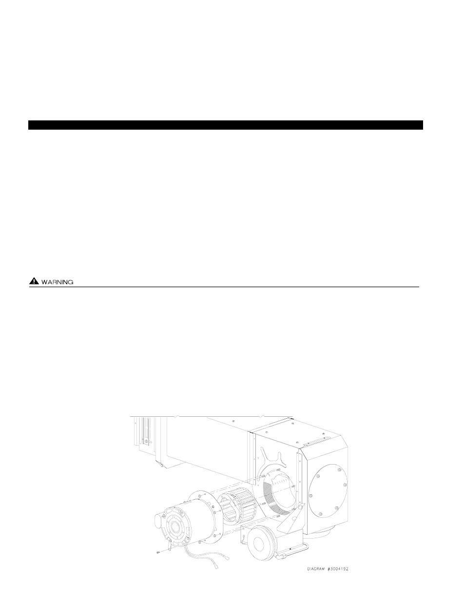
REMOVAL AND REPLACEMENT OF MOTOR/WHEEL ASSEMBLY (DIAGRAM N)
Disconnect power supply from the SS1C and heating equipment when making wiring connections and servicing the SS1C.
Failure to do so may result in personal injury and/or equipment damage. LED #5 (RED) should be off with power removed.
1. Remove electrical box cover.
2. Disconnect the two motor leads from the MTR & N terminals.
3. Remove motor bracket screw from electrical box.
4. Holding the motor, apply firm pressure towards the plenum of the SideShot and remove the six motor mount nuts. Note: Hold
the assembly firmly; failure to do so could damage internal parts.
5. Slide motor/wheel assembly from Plenum. Grasp only the motor casing; do not damage wheel, shaft or other components on
Plenum. Do not rest assembly on wheel.