Tjernlund SS1C SideShot with UC1 Universal Control (Version X.04) 8504103 Rev C 02/04 User Manual
Page 17
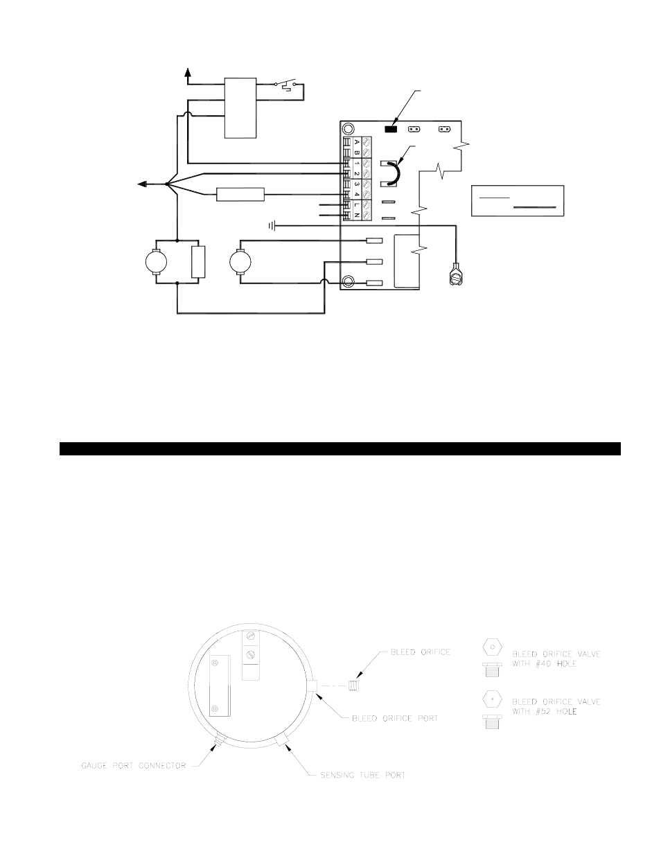
SELECTION OF PRESSURE SWITCH BLEED ORIFICE
In order for the SideShot pressure switch to function properly for the intended application, the proper bleed orifice has to be
selected as determined below.
1. Upon installation, if the vent connector length is less than 3.1 equivalent meters (10 feet), then the smaller
opening #52 bleed orifice should be used.
2. Upon installation, if the vent connector length is greater than 3.1 equivalent meter (10 feet), then the larger
opening #40 bleed orifice should be used .
3. Once proper bleed orifice has been determined, install into the Bleed Orifice port as indicated.
16
DIAGRAM P
SIDESHOT WITH INTEGRAL UC1 UNIVERSAL CONTROL CONNECTED WITH A HONEYWELL R8184
SERIES OR EQUIVALENT PRIMARY CONTROL AND A BURNER MOTOR POST-PURGE
1. Separate the burner motor wire and ignition transformer from the Orange wire of R8184.
2. Connect the Orange of R8184 to #1 on UC1 terminal block.
3. Connect #2 on UC1 terminal block to White on R8184 and L2 or B2.
4. Connect the HOT wire of oil solenoid valve to #4 on UC1 terminal block and neutral wire to White or N.
5. Connect burner motor and ignition transformer HOT wires to M terminal on UC1 and neutrals to White or N.
6. Connect 115 VAC supply voltage to L & N terminals on UC1. Installer must supply overload and disconnect protection.
7. Crimp ground wire to grounding spade in SS1C electrical box.
8. Make sure RED voltage jumper on UC1 is on 115V.
RED JUMPER POSITION MUST BE THE SAME
AS APPLIANCE INTERLOCK VOLTAGE.
U
N
IVER
SAL
C
O
N
T
R
O
L
XN
BURNER
NM
T
R
M
THERMOSTAT
OIL VALVE
W
O
WHITE
ORANGE
B
F
F
T
T
IMPORTANT:
XL
J1
J2
115V
DRY
24V
115 VAC
LEGEND:
CALL
JUMPER
BLACK
HONEYWELL R8184
SERIES OR EQUIVALENT
VENTER
MOTOR
MOTOR
IGNITION
TRANS
50/60 Hz
SUPPLY
115 VAC
SPADE TERMINAL IN ELECTRICAL BOX.
GROUND
CRIMP GROUND WIRE TO GROUNDING
IMPORTANT:
D/N 9183047-4 10/16/03
L1 OR B1
CONNECT TO
CONNECT TO
L2 OR B2