Tjernlund DJ-3, D-3, HD, I, IL, XL Draft Inducer 8504003 Rev A 07/00 User Manual
Page 3
INSTALLATION RESTRICTIONS
Failure to install, maintain and/or operate the Draft Inducer in accordance with manufacturer's instructions may result in conditions
which can produce bodily injury and property damage.
The Draft Inducer must be installed by a qualified installer in accordance with these instructions and all local codes or in their absence
in accordance with the latest editions of The National Fuel Gas Code (NFPA #54), Installation of Fuel Burning Equipment (NFPA 31),
Chimneys, Fireplaces, Vents, and Solid Fuel Burning Appliances (NFPA 211), The National Electrical Code (NFPA#70) and the
Occupational Safety and Health Act (OSHA) when applicable. Improper installation can create a hazardous condition such as an
explosion, fire, electrical shock or carbon monoxide poisoning resulting in property damage, personal injury or death.
1. The Draft Inducer shall not be used on condensing heating equipment.
2. Oil burning installations and gas-fired units without a draft hood / diverter should include a barometric draft regulator.
3. The Draft Inducer motor shaft must be mounted horizontally to prevent motor bearing wear.
4. The Draft Inducer shall not be installed where flue gas temperatures exceed 575
O
F at the Draft Inducer Inlet. Ambient room
temperatures must not exceed 104 degrees F.
Flue gas temperature verification:
A) Consult appliance manufacturer for temperature of gases at the appliance outlet after dilution by draft hood, draft diverter or
barometric draft control.
AND
B) Measure temperature of flue gases at the Draft Inducer inlet at time of installation. Temperature should be measured after
appliance and Draft Inducer have operated for at least 10 minutes, allowing flue gas temperature to stabilize.
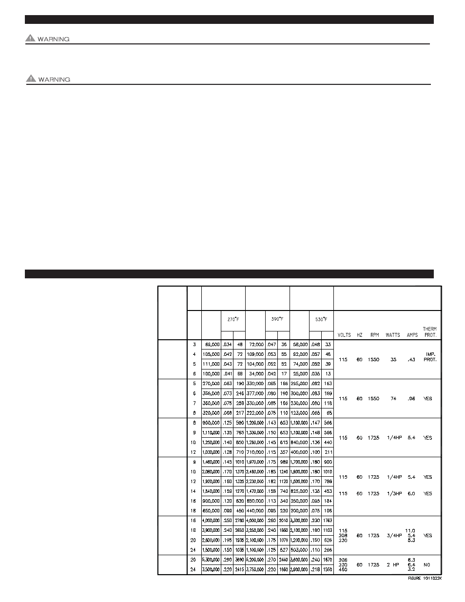
DRAFT INDUCER SELECTION TABLE
2
1. Inputs shown are believed to be
maximum capacities for inducers when
mounted on pipe sizes shown for
ordinary jobs where a moderate amount
of mechanical induced draft is required.
2. Consideration is given to typically
higher static pressure requirements for
larger installations, for the type of fuel
burned and for the type of draft control
installed.
3. Where pressure requirements are
unknown or believed to be unusually
severe, ask for complete performance
curves or consult factory.
4. All ratings have been developed in our
testing and research department and
have been approved by a nationally
known independent testing laboratory.
Certification is available upon request.
5. Heating capacities shown are for 1000
BTU per cubic foot natural gas and for
139,000 BTU per gallon No. 2 fuel oil.
Consult factory for capacities with other
fuels. Heating capacities are based on
typical combustion efficiencies and
allow for approximately 5 percent
ambient air drawn into inducer to
cool motor and drives.
6. Draft Inducers should be installed
in single wall vent pipe in order
to insure proper performance.
DJ-3
D-3
I
IL
XL
HD
GAS FIRING
WITH
DRAFT HOOD
MODEL
GAS FIRING
WITH
BAR. DRAFT
CONTROL
OIL FIRING
WITH
BAR. DRAFT
CONTROL
HEATER
BTU
INPUT
HEATER
BTU
INPUT
HEATER
BTU
INPUT
S.P. CFM
CFM
S.P.
CFM
S.P.
FLUE GAS
FLUE GAS
FLUE GAS
ELECTRICAL
DATA
IN.
SIZE
PIPE