Lobe port pins, The 9t428-16 module, Lobe port pins -7 – Cabletron Systems 9T428-16 User Manual
Page 21: The 9t428-16 module -7
2-7
Installation
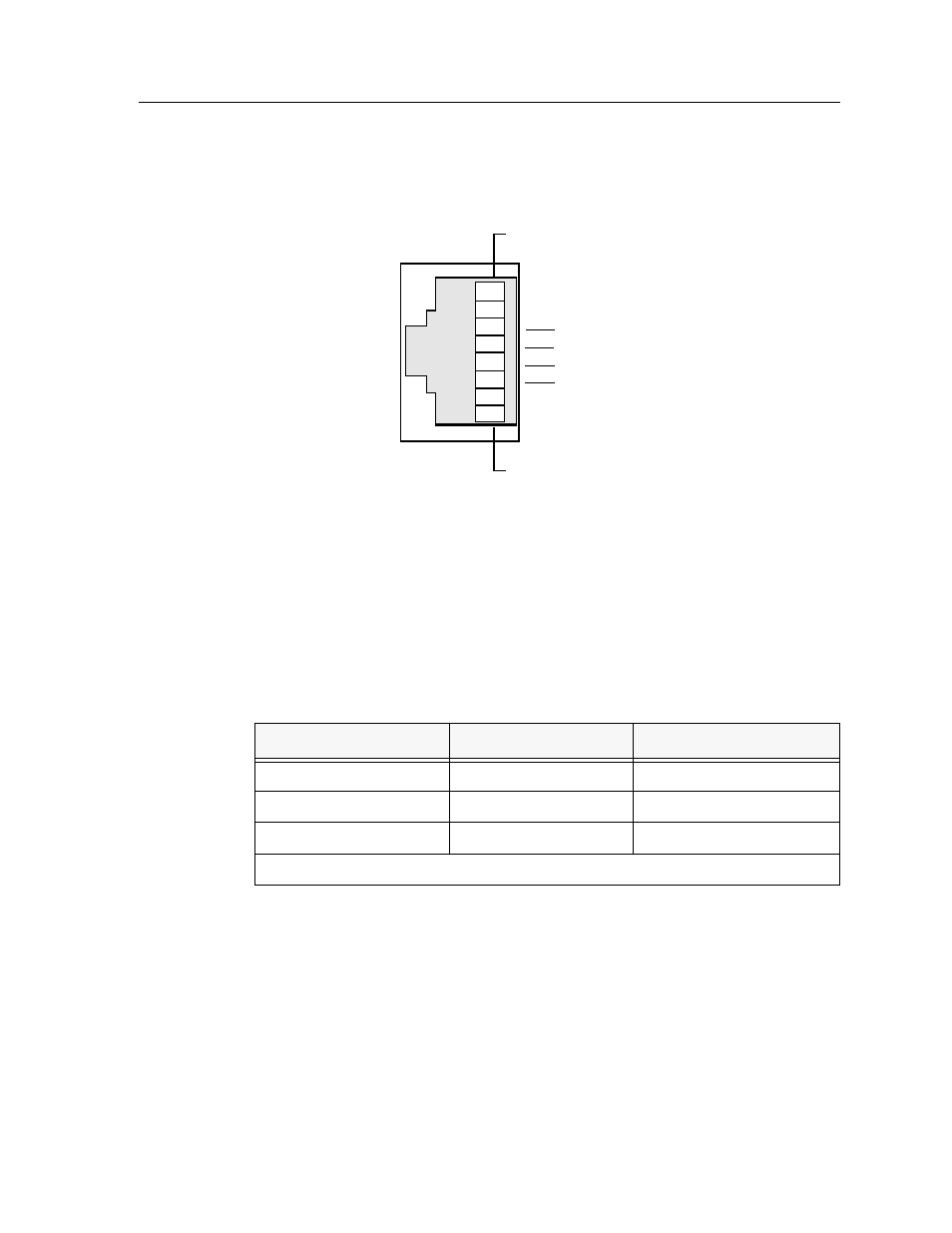
Lobe Port Pins
Figure 2-5 illustrates the signal assignments for RJ45 lobe port pins.
Figure 2-5. RJ45 Lobe Port Pins – Signal Assignments
The 9T428-16 Module
Table 2-2 lists signal tolerance speciÞcations for the Multimode Fiber Optic cable
used for front panel connections.
The Fiber Optic cable segments have ST connectors. They are connected by
inserting the connector in the port and then turning it to lock down.
The Receive port of one device is connected to the Transmit port of the other
device as shown in Figure 2-6.
Table 2-2. Signal Tolerances for Multimode Fiber Optic Cable
Cable Type
Attenuation
Maximum Drive Distance
Multimode 50/125
µ
m
≤
13.0 dB
2 km (2187.7 yards)
Multimode 62.5/125
µ
m
≤
16.0 dB
2 km (2187.7 yards)
Multimode 100/140
µ
m
≤
19.0 dB
2 km (2187.7 yards)
Typical Signal Attenuation Rate:
≤
1.5 dB/km
Rx-
Tx+
Tx-
Rx+
1
2
3
4
5
6
7
8
Cable Shield
Cable Shield