Smart Power Systems SSP UPS User Manual
Page 38
35
6. BATTERY REPLACEMENT
7. Slide the new batteries into EBM.
8. Reconnect the battery cable and screw the battery bracket.
9. Close and reinstall the front panel back to EBM.
7. COMMUNICATION PORT
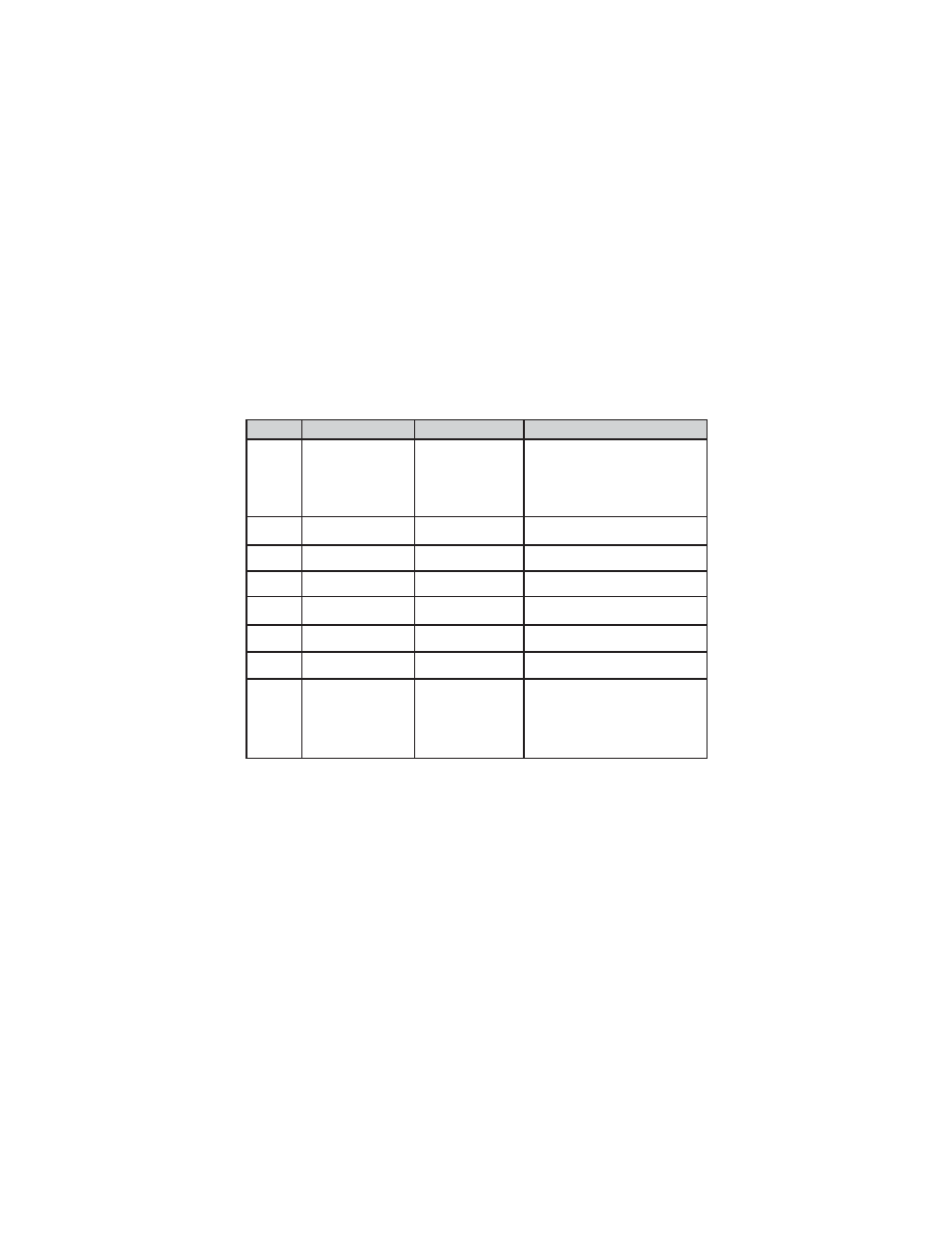
7.1 RS232 + Dry contact (750/1000/1500/2000/3000VA):
DB9 Female (RS232 +dry contact)
7.2 USB port: HID protocol
The USB and RS232 are unable to operate at the same time. Either the USB
or DB9 can connect with RS-232 at one time, usually connecting with USB
function is priority.
PIN #
Description
I/O
Function Explanation
1
DCD
Output
Low Battery Output
(*normally open, pull to
Pin# 5 when battery low
alarm in battery mode)
2
RxD
Output
RxD
3
TxD
Input
TxD
4
5
Common
--
6
DSR
Output
7
RTS
Input
No connection
8
(tied to pin 6)
Input
DTR
Common (tied to chassis)
(tied to pin 4)
AC Fail Output
(*normally open, pull to
Pin#5 when UPS is in
battery mode).
Output
CTS