Operation – Smart Power Systems HR-30 User Manual
Page 28
Smart Power
®
Systems
A. C. MODULAR GENERATOR SYSTEM
Page 27 of 50
Operation
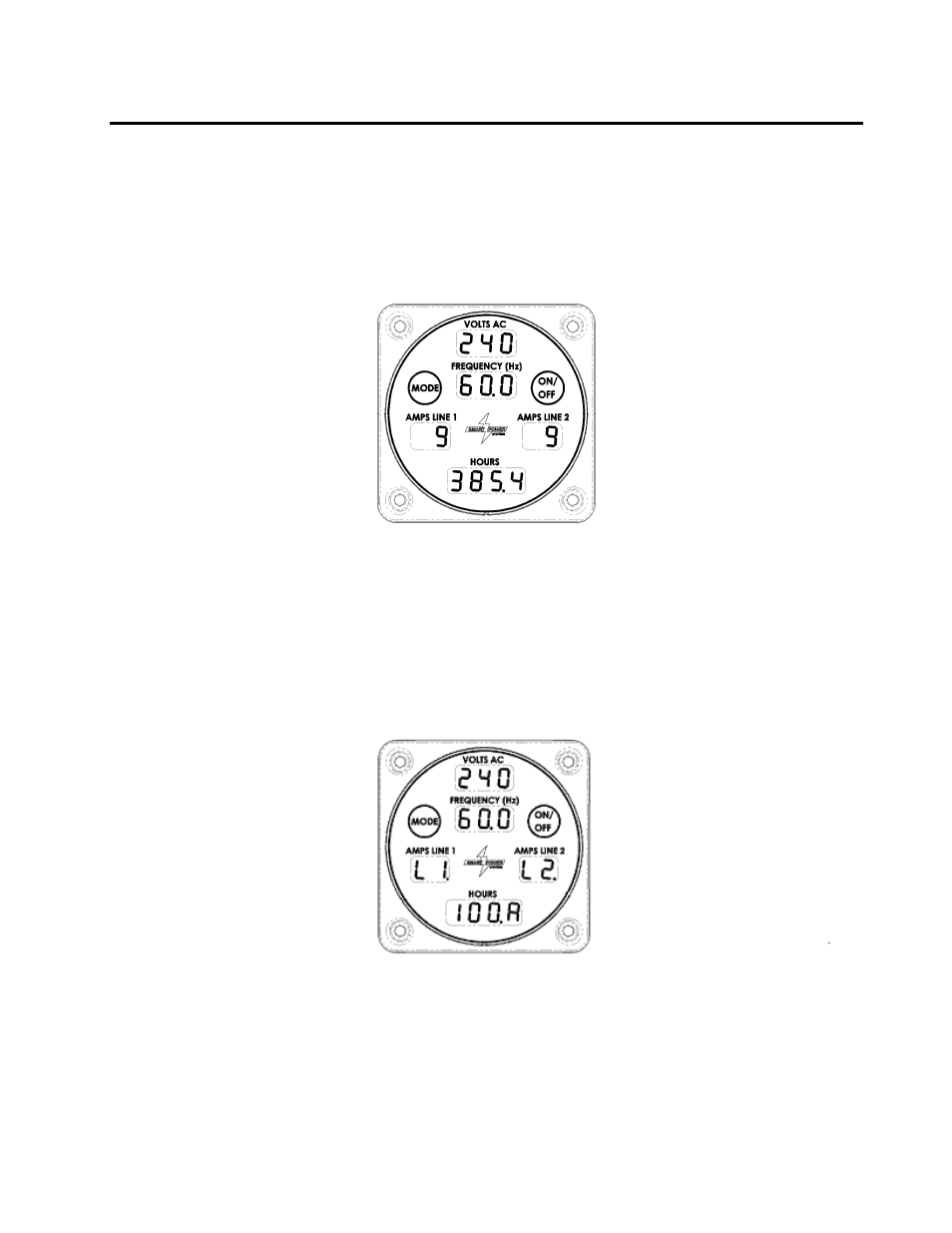
1A. The Command & Control Center will show the generator’s output voltage,
frequency, current, and system run time whenever the Command & Control Center
is in the Normal mode. To access Normal mode, press the Mode switch repeatedly
until the correct information is displayed (reference Figure16A).
Example of Command & Control Center in Normal Mode
Figure 16A
1B.
When system current draw is 100 amps or more, the current will be displayed in the
‘HOURS’ window instead of the AMPS window. The designator ‘L1’ or ‘L2’ will be
shown in the corresponding AMPS window (reference Figure16B). If BOTH L1 and
L2 are over 100 amps, then each of the two currents will be alternately, over about
3 seconds, shown in the HOURS window.
Example of Command & Control Center in 100+ AMP Mode
Figure 16B
2.
The PTO driving the SPS hydraulic pump must be engaged for the system to
generate electricity.
3.
The Command & Control Center is equipped with two Smart Touch
®
switches,
labeled “Mode” and “On/Off” respectively. These switches do not require pressure
to be activated, but instead sense the presence or absence of your fingertip. The