Thermostat replacement procedure, Renewal parts identification – Chromalox PF421-6 User Manual
Page 3
3
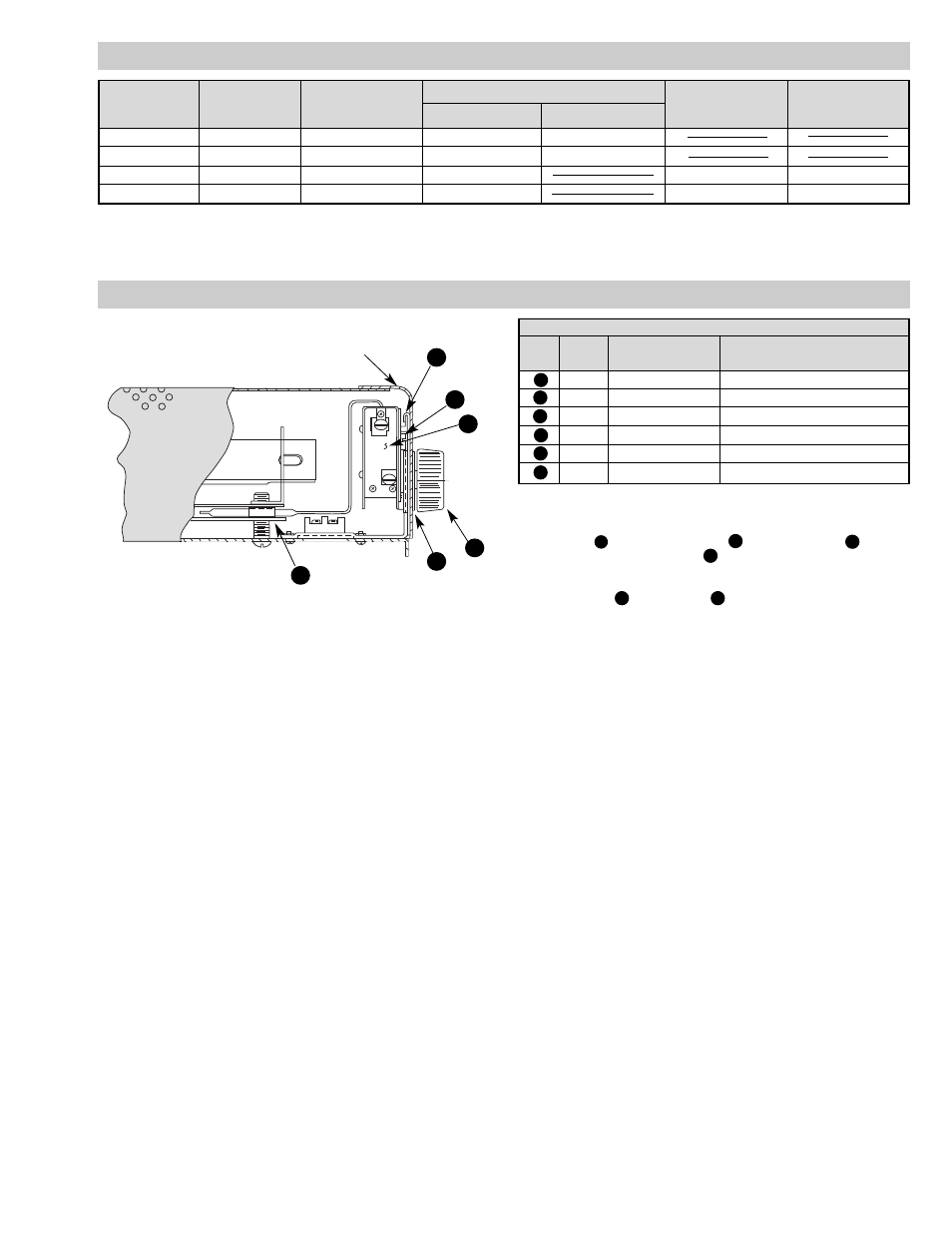
THERMOSTAT REPLACEMENT PROCEDURE
Thermostat Kit (168-073659-001)
Item
No.
Qty.
Part No.
Description
1
1
300-072275-007
Thermostat
2
1
027-073304-002
Bracket — Mounting
3
2
248-048179-020
Screws
4
1
220-072276-003
Plate-Dial Thermostat
5
1
169-073294-001
Knob
6
1
056-073305-001
Clamp — Capillary Bulb
1
2
3
4
5
6
See Instruction #4
See Instruction #1
Thermostat Replacement Instructions:
1. Remove cover.
2. Slide thermostat mounting bracket over existing plate.
3. Using item
3
(screws) assemble item
1
(thermostat) to item
2
(bracket).
4. Remove bolt and assemble item
6
capillary clamp and capillary bulb and
re-install bolt. Note: Do not pinch bulb in clamp, thermostat decalibration
will result.
5. Assemble item
4
(plate) and item
5
(knob).
6. Re-install cover.
RENEWAL PARTS IDENTIFICATION
Heating Elements
Front
Terminal
Thermostat Kit
Model
Watts
Cover
120V
240V
Block
(See Below)
EH-1221
250
080-016362-002
285-051049-001
285-051049-002
EH-1251
500
080-016362-002
285-051049-001 (2)
285-051049-002 (2)
HVT-1251
500
080-016362-003
285-051049-006
303-047610-005
168-073659-001
HVT-2411
1000
080-016362-003
285-051049-006 (2)
303-047610-005
168-073659-001
Note: Part numbers suffixed by a number in ( ) indicates the quantity of same part number used.