Origin Live Aurora Gold Platter Driven User Manual
Page 9
Page 9
U S E O F S T Y L U S F O R C E G U A G E
Most stylus force gauges work on the same principle as a set of
scales or balances. For example with the Ortofon Stylus Force
Gauge, first place the stylus on the inscribed or graduated
portion of the scales. Then try the stylus at different points
until you find the point where the beam “balances” freely in
a roughly level position. You then read the force that is being
exerted –( 1gram = 10 mN if the scale is in mN). From this
number you can assess whether you need to increase the
tracking force or vica-versa. Move the tonearm counterweight
accordingly and re-measure the tracking force. Repeat this
procedure until the correct tracking force is obtained. The
Shure stylus force gauge works slightly differently so follow the
instructions that come with the gauge.
S I D E B I A S F O R C E
Once the tracking force has been set you can set the sliding control for
tracking bias - This should be set to a value of approximately 1 or less due
to the fact that the bias adjustments on Rega arms and similar arms tend
to under-read the true value of side force produced. . The settings you read
on the Rega, OL1 or Silver arms are not always dead accurate so it may be
worthwhile to fine tune the setting using the following method. Find a test
record or a record with approx 10mm of blank vinyl between the end of the
lead out groove and the record label. Place the stylus needle on the blank
uncut vinyl and see whether the needle skates inwards towards the centre
of the record or outwards. You are aiming to achieve a situation where the
needle drifts slowly towards the centre of the record so adjust the side bias
until this state is reached.
As the stylus tracks across a record it experiences forces that
tend to push it towards the centre of the record. To counteract
this force the arm is best set up with an approximately equal
and opposite force called the “side bias”
On Rega, OL1 and Silver arms the side bias force is set using
the small sliding knob located beside the lift lower lever.
On the Encounter, Illustrious and Conqueror arms – Carefully
twist the wire loop to the correct angle relative to the arm base
– you can use the enclosed plan view of the arm to do this
– the angle only needs to be approximate – the wire loop is
held in place by a set screw at it’s base – this can be retightened
if necessary using the 1.5mm allen key supplied.
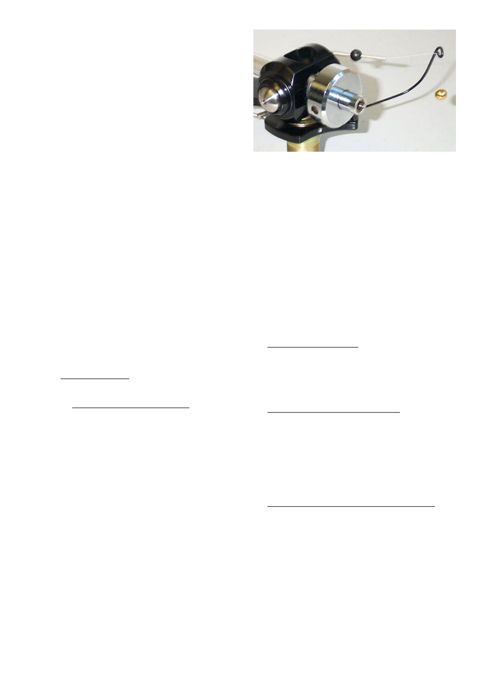
Carefully unpack the 2 balls and joining thread. Set up the 2
balls and thread as shown in photo below. The side bias force is
set using the ball which slides along the silver shaft protruding
from the rear of the arm yoke (beside the counterweight)
- see photo below. This ball is clamped in position using a set
screw in the ball with 1.5mm allen key. Thread the thin nylon
filament line through the small gap of the wire “eye” to allow
the ball weight to hang freely. The adjustment ball is initially
set at just under three-quarters of the way out along the silver
rod – this is approx the correct position for most cartridges. If
you wish to increase the side bias force then unclamp the ball
using a 1.5mm Allen key and the ball further outwards. To
decrease the side force move the ball inwards. Once you have
finalised the correct position re-clamp the ball in position.
S E T T H E V T A ( V E R T I C A L T R A C K I N G
A D J U S T M E N T )
To allow the cartridge needle to track at the correct angle it is necessary that
the base of the arm is at the correct height in relation to the platter. Usually
the optimum setting is such that the TOP edge of the arm is parallel with
the surface of a FLAT record – you can use a piece of card with parallel lines
drawn on it to check this. Place the cartridge on the record with the deck
switched off. Hold the card edge onto the record in a position alongside
the arm and see whether the top edge of the arm is parallel.. Raise or
lower the base of the arm till you achieve parallel position. Most cartridges
have a height of 17mm. If this is the case, the base of the arm should rest
approximately 31mm below the top of the platter surface –see diagram
“cross-section of sub-chassis”.
It is worth experimenting with VTA adjustment. Slightly raise or lower the
arm and then listen - if the sound is relatively bright then the arm is too
high, if it is relatively dull and bass heavy then the arm is too low.
If you have no VTA adjuster Raise and lower the arm
by fitting spacing washers under the arm. Alternatively
you can raise or lower the height of the platter – this
is easily accomplished by removing the platter to re-set
the height of the threaded bearing house (see “diagram
showing threaded bearing house arrangement”).
If you have the threaded VTA adjuster Raise and
lower the arm by rotating the VTA adjuster. If you find
your arm is too high in relation to the platter with the
VTA adjuster set to give the arm it’s lowest position
then you need to raise the height of the platter a few
millimetres – this is easily accomplished by removing
the platter to re-set the height of the threaded bearing
house (see “diagram showing threaded bearing house
arrangement”).
If you have the Origin Live VTA sliding adjuster
– Raise and lower the arm in the aluminium sleeve and
then clamp it in position via the set screw in the side
of the VTA housing (i.e the sleeve is forced in to grip
the arm’s threaded base). You do not need the Rega
nut on the base of the arm. Only tighten the set screw
just sufficiently to clamp the arm in position – over-
tightening can make the arm sound relatively bright.
S E T T H E A R M F A S T E N I N G
T I G H T N E S S
It is best to experiment with the tightness of the large Rega base nut (if
fitted) by listening to music. This may seem laborious but you will be richly