Notice, Warning, Powerreclinexr – La-Z-Boy PowerReclineXR after 01/19/2015 User Manual
Page 7: Rocking loveseat assembly instructions
13
12
PowerReclineXR
®
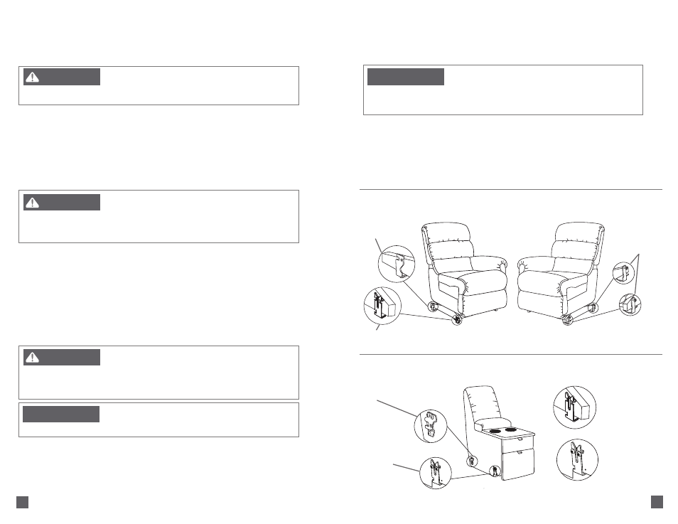
Rocking Loveseat Assembly Instructions
F
IGURE
1
Left Side (Sitting) Rocker Recliner
Front Attachment
Bracket
F
IGURE
3
F
IGURE
4
Console
Front Side
Mount “U”
Bracket
Front Attachment
Bracket (Console)
Front Attachment
Bracket (Left Side
Sitting Rocker
Recliner)
Rear
Side
Mount
Bracket
Threaded
Studs
F
IGURE
2
Right Side (Sitting) Rocker Recliner
8. The units must be disconnected before moving the loveseat. To disconnect the units, lift up the left front
corner of the right side (sitting) recliner approximately 3" to clear the front attachment bracket on the
console. Move the recliner to the side before returning it to the floor. Slide the right side (sitting) recliner
backward to disengage the back bracket on the console. Repeat these steps to disconnect the console
from the left side (sitting) recliner.
9. Proceed to the Battery Backup Assembly Instructions.
NOTICE:
– To reduce the risk of product damage:
• Do not move the units while connected together. The purpose of the bracket system is to
connect the units and prevent them from being separated while on the floor. The bracket
system does not provide adequate structural support for the movement of connected units.
Rear Bracket
PowerReclineXR
®
Rocking Loveseat Assembly Instructions
1. Place the furniture in the desired location; refer to Furniture Placement Guide.
2. Use a T-30 torx driver to loosen the threaded studs to approximately 1"; this measurement may vary
depending on the fabric and style. The threaded studs are located on the left side (sitting) of right side
(sitting) units.
3. Place the console (F
IGURE
3) approximately 2" to the side of the left side (sitting) rocker recliner (F
IGURE
1).
Position the console (with the threaded studs) slightly behind the recliner. Separate the fronts of the units
to be connected, about 6" apart. Pull the console forward until the threaded stud on the console engages
in the rear bracket on the recliner.
– To reduce the risk of serious injury:
• Provide a clear path for operation of the back and legrest. Place tables and area rugs
at a distance to allow the legrest to fully extend without rubbing or interference.
WARNING
– To reduce the risk of serious injury:
• The front of the unit must be raised to engage the front bracket. Please seek assistance if
you are unable to lift at least 21 pounds.
• Keep feet clear of the unit when lowering into position.
WARNING
4. Lift the front of the console approximately 3" off the ground, aligning it to the attachment bracket on the
left side (sitting) rocker recliner. Gently lower the threaded stud into the front attachment bracket (F
IGURE
4).
Keep feet clear of the unit when lowering into position.
NOTE:
Due to variations in upholstery and style, the threaded stud length may need to be adjusted to fit
into the attachment brackets or control gaps between units. Loosen or tighten the threaded studs to provide
adequate clearance.
5. Place the right side (sitting) rocker recliner (F
IGURE
2) about 2" to the side of the console. Position the right
side (sitting) rocker recliner (with the threaded studs) slightly behind the console. Separate the fronts of
the units to be connected, about 6" apart. Pull the right side (sitting) recliner forward until the threaded
stud on the recliner engages in the rear bracket on the console.
NOTICE:
– To reduce the risk of product damage:
• Lift from the side frame. Do not lift from the upholstery or bottom of the legrest.
– To reduce the risk of serious injury:
• The front of the unit must be raised to engage the front bracket. Please seek assistance if
you are unable to lift at least 21 pounds.
• Keep feet clear of the unit when lowering into position.
WARNING
6. Lift the front of the right side (sitting) recliner approximately 3" off the ground, aligning it to the attachment
bracket on the console. Gently lower the threaded stud into the front attachment bracket. Keep feet clear
of the unit when lowering into position.
7. Adjust the glides on the console to level the unit, if necess ary. Turn clockwise to lower and
counterclockwise to raise.
(Assembly Instructions Continued)