Notice, Warning, 1ct) comforttouch – La-Z-Boy ComfortTouch Adjustable Firmness Recliner User Manual
Page 4
(1CT) ComfortTouch
™
Adjusta ble Fir mness Recliner
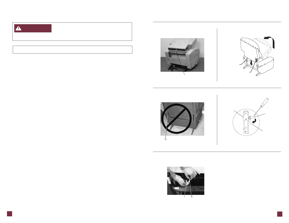
Assembly Instr uctions:
F
I G U R E
1
Body
Bracket
Back Bracket
Back
Bracket
Locking
Lever
Locked
Position
F
I G U R E
3
Back Air Hose
7
6
1. Install the back.
•
Lay the back across the chair ar ms . The air hose on the bottom of the
upholstered back must fall between the rear rail and the seat (F
IGURE
1).
Lift the back at a slight angle and align the brackets on the back with the
brackets on the body (F
IGURE
2).
•
Lower the back onto the body, making sure the back and body brackets are
completely engaged.
•
To make sure the back is proper ly installed, with both sets of back
and body brackets engaged, stand behind the chair and twist the
back from side to side. If one or both sides move out of position
the brackets are not engaged (F
IGURE
3). Remove the back and
repeat the steps a bove.
•
If you are unable to install the back properly contact your La-Z-Boy
®
dealer for assistance.
•
Lock the brackets by using a screwdriver to push down the locking levers (F
IGURE
4).
2. Gently roll the chair forward to rest on front of the chair body. Locate the air
hose connector from the back and the air hose connector from the motor.
The seat air hose connection comes already attached.
3. Fasten the air hose connector from the back to the air hose connector from
the motor (F
IGURE
5).
•
Twist the air hose coming from the back counterclockwise, a pproximately
two tur ns , and hold. The counterclockwise twist in the back air hose
makes the connection easier and ensures a tighter fit to prevent air
leaks at the joint.
•
Inser t the air hose connector from the back into the air hose connector
from the motor and tur n clockwise to fasten the threaded connector s .
(Assembly Instructions Continued)
(1CT) ComfortTouch
™
Adjusta ble Fir mness Recliner
Assembly Instr uctions:
–
To reduce the risk of injur y:
•
Do not operate the unit until the back is installed and locked.
NOTICE:
Do not plug in until instructed.
F
I G U R E
2
Motor Air Hose
Connector
F
I G U R E
5
F
I G U R E
4
Back and body brackets on this
side are not engaged. Remove
the back and reinstall.
Back Air Hose
Connector
WARNING