3 installing the liveusb drive, 4 installing the power supply (power brick), 5 installing user added options – Kontron M2M Smart Services Developer Kit User Manual User Manual
Page 20
20
3.3
Installing the LiveUSB Drive
The Kontron M2M Smart Services Developer Kit comes with a USB drive that provides software demos that can be
inserted into your workbench PC. Please
see the Getting Started Guide available in the “downloads” section of the
Kontron M2M Smart Services Development Kit product page on
3.4
Installing the power supply (power brick)
WARNING: Do not attempt to modify or use an AC power cord set that is not the exact type supplied. Note
that the power supply in the kit is a Delta EADP-24MB A.
The power supply that accompanies the Kontron M2M Smart Services Developer Kit is the only one that
should be used. Use of any other power supply invalidates the certifications and may be dangerous.
To install the power supply (external power brick) follow these steps:
1. Attach the cord for your geography to the power supply. The power supply is external to the M2M
system. It is a brick style.
2. Insert the power supply plug into the power socket on the top of the M2M System.
3. Plug in the cord to the wall socket.
3.5
Installing User Added Options
Installing a SIM Card
Most countries worldwide have one or more operators that support 3G data services; please check with your local
operator as to whether the operator supports HSPA, WCDMA or EDGE data services. All three are supported by the
Ericcson F5521gw module. Please obtain your SIM from your local 3G operator (only selected custom SKUs from
Kontron include a SIM). The SIM may be easily inserted in the slot on the top of the M2M System. A SIM card must
be added to 3G M2M Systems to support 3G connectivity supplied by the Ericcson 5521gw module.
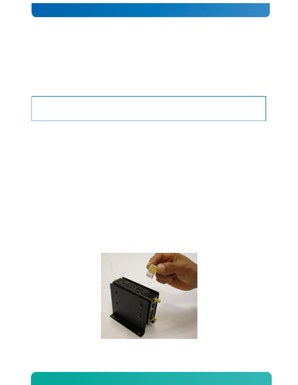
To install your SIM card position the SIM so that the contacts are facing the non-labeled side of the M2M System as
shown (with the
contacts facing the headphone jack side of the system)
. The notch in the SIM card should on
the lower left as shown in Figure 15.
Figure 15. Positioning of the SIM card pre-insertion in the M2M System