Grounding stud, Side view, Fig. 18: grounding stud – Kontron KISS 1U PCI 762 User Manual
Page 21: Fig. 19: side view
7. Product Description
KISS 1U_SBC_762 – User's Guide (Version 1.00)
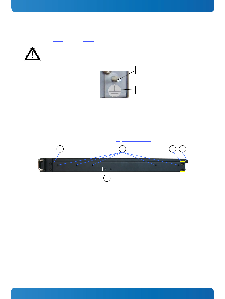
7.2.3. Grounding Stud
The grounding stud (Fig. 15, pos. 10 and Fig. 18) is located on the rear side of the KISS 1U platform
The KISS 1U systems with grounding studs can be connected to a “common ground” connection point.
Grounding stud
Fig. 18: Grounding stud
7.3. Side View
Five M4 metric tapped holes are available at the left and right side of the unit.
These can be used in order to attach slide rails (not included in the scope of delivery) to the KISS 1U (for system
installation into a 19" industrial cabinet). Refer to the chapter 11 “Slide Rails (Option)”.
1
4
3
2
Ground label
5
Fig. 19: Side view
1 Right side view of the KISS 1U
platform
2 5x tapped M4 metric holes (on
both sides)
3 Mounting screws of the add-on
card slots
4 Cover with captive knurled screws (for
fixing the device cover)
5 Screws for fixing the card holder
position (adjustable) (Fig. 20, pos. 7)
www.kontron.com
19