3 msd connector jp3, 4 auxiliary connectors and signals – Kontron CP3-BP8-P47-RIO User Manual
Page 9
CPCI Backplane
PD06: CP3-BP8-P47-RIO
RID 24229 PD06, Rev. 01
© 2002 PEP Modular Computers GmbH
Page 9
5.3
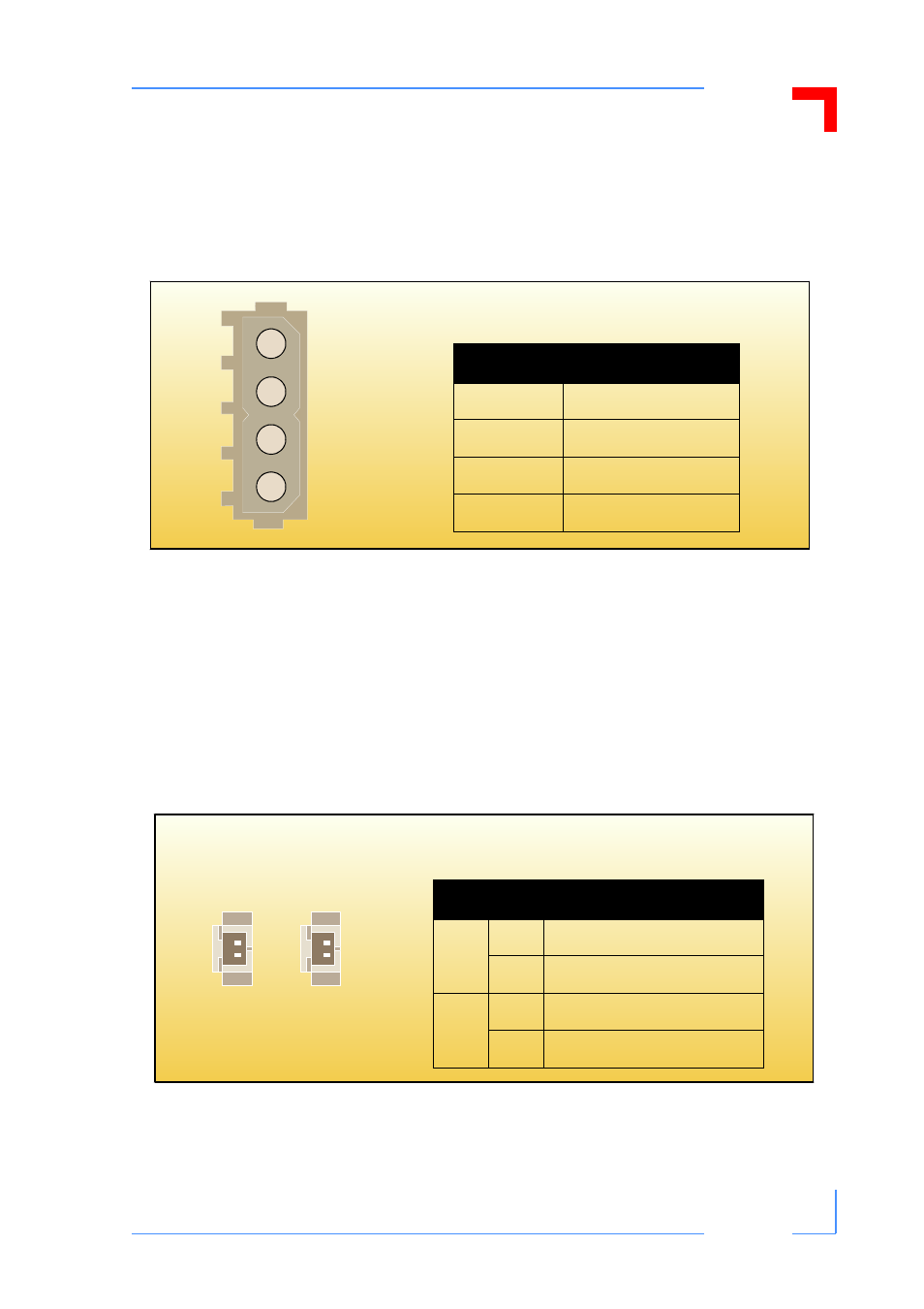
MSD Connector JP3
One 4-contact female connector is installed on the backplane for the connection of mass stor-
age devices (drives) to the +5V/+12V
power supply of the bus.
Figure 5:
Orientation and Pinout of the CP3-BP8-P47-RIO MSD Connector
5.4
Auxiliary Connectors and Signals
There are two, two-contact, male auxiliary connectors, JP16 and JP17, available on this back-
plane.
JP16 and JP17 make the signal lines, PRST and INH# respectively, available for external
switches to either invoke a system reset or to switch the power supply on or off.
No other auxiliary signals are made available externally on the this backplane.
Figure 6:
Orientation and Pinouts of CP3-BP8-P47-RIO Connectors JP16 and JP17
1
2
3
4
Table 6: Pinout of CP3-BP8-P47-
RIO MSD JP3 Connector
Pin
Function
1
+12V
2
GND
3
GND
4
+5V
1
2
JP17 JP16
Table 7: Pinouts of CP3-BP8-P47-RIO
Connectors JP16 and JP17
Pin
Function
JP16
1
GND
2
PRST
JP17
1
GND
2
INH#