Jp12, Jp11 – Kontron CP3-BP8-P47-RIO User Manual
Page 11
CPCI Backplane
PD06: CP3-BP8-P47-RIO
RID 24229 PD06, Rev. 01
© 2002 PEP Modular Computers GmbH
Page 11
5.6
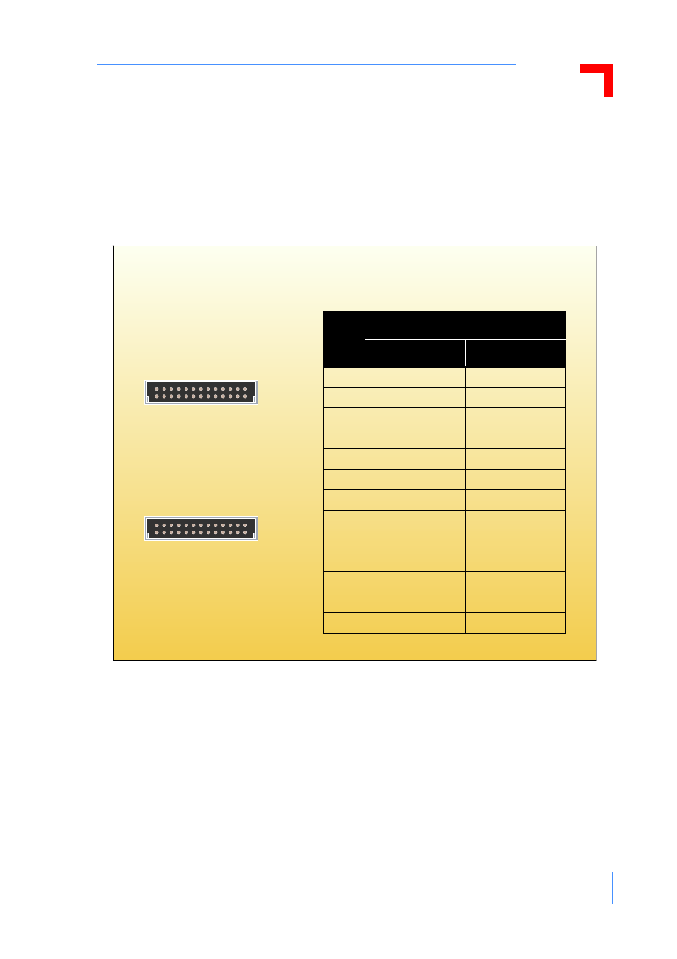
System Monitor and Control Connectors JP11 and JP12
This backplane is provided with two connectors for system monitor and control signal interfac-
ing to external devices. Both are 26-contact, male, double pin-row connectors, and have the
same signal pinout configuration. The system management bus (IPMB0), the power supply
monitor and control signals, and push button reset (PRST#) signal are all implemented on
these connectors.
Figure 8: Orientation and Pinout of the CP3-BP8-P47-RIO SMC Connectors JP11 and JP12
1
13
b
a
JP12
1
13
b
a
JP11
Table 9: Pinout of CP3-BP8-P47-RIO
SMC Connectors JP11 and JP12
Pin
Function
Pin Row A
Pin Row B
1
IMPB0_SCL
GND
2
IMPB0_SDA
IMPB0_PWR
3
N/C
GND
4
N/C
GND
5
N/C
GND
6
INH#
GND
7
FAL#
DEG#
8
PRST#
GND
9
GND
V1 SENSE (+5V)
10
V2 SENSE (+3.3V)
SENSE RTN
11
V3 SENSE (+12V)
GND
12
V1 SHARE (+5V)
V2 SHARE (+3.3V)
13
V3 SHARE (+12V)
GND
- CP3003-SA uEFI BIOS (72 pages)
- CP3003-SA (36 pages)
- CP3002 (38 pages)
- CP3002-RC uEFI (64 pages)
- CP-RIO3-05 (42 pages)
- CP3002-RC (30 pages)
- CP342 (52 pages)
- CP930 (46 pages)
- CP932 (52 pages)
- CP346 (72 pages)
- CP384 (66 pages)
- CP383 (74 pages)
- CP382 (58 pages)
- CP381 (60 pages)
- CP372 (64 pages)
- CP371 (60 pages)
- CP-RIO3-04S (38 pages)
- CP390 (36 pages)
- CPS3410 (9 pages)
- CPS3402 (9 pages)
- CPS3105 (9 pages)
- CPS3101 (9 pages)
- CPS3003-SA (19 pages)
- PB-SIO4 (34 pages)
- PB-SIO4A (34 pages)
- PB-DOUT8 (34 pages)
- VMOD-2 (82 pages)
- VSBC-32 (110 pages)
- VM42 (62 pages)
- Bootstrap Loader (24 pages)
- VMP1 with Netbootloader (120 pages)
- VMP1 (106 pages)
- NetBootLoader (86 pages)
- VMP2 (142 pages)
- VMP3 (154 pages)
- CP-RIO6-923 (32 pages)
- CP-RIO6-923-F (32 pages)
- CP-RIO6-001 (28 pages)
- CP-RIO6-001-HD-VGA (46 pages)
- CP-RIO6-M (20 pages)
- CP-RIO6-B (28 pages)
- CP6925 (42 pages)
- CP6002 uEFI BIOS (76 pages)
- CP6002 IPMI (40 pages)
- CP6002 (42 pages)