3 installation – Kontron CP3-SVE-P200DC-24V User Manual
Page 7
Page 7
CPCI Power Supply
PD14: CP3-SVE-P200DC-24V
RID 24139 PD14, Rev.02
2.3
Installation
Thanks to its plug-in compatibility this P-type power supply unit allows for an easy installation,
by which the power supply unit’s male Positronic 47-pin power connector is inserted into the
backplane’s mating female connector without the need of any intermediate adaptation.
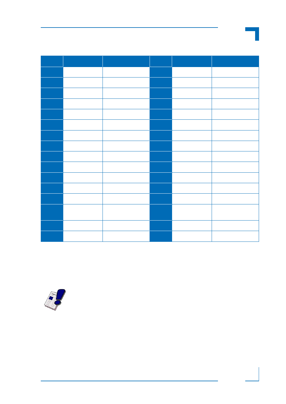
Table 2: Positronic 47-Pin Connector Pinout
PIN
SIGNAL NAME
DESCRIPTION
PIN
SIGNAL NAME
DESCRIPTION
1 - 4
V1
V1 OUTPUT (+5V)
32
NC
NOT CONNECTED
5 - 12
RTN
V1 and V2 RETURN
33
V2 SENSE
V2 REMOTE SENSE
13 - 18
V2
V2 OUTPUT (+3.3V)
34
S RTN
SENSE RETURN
19
RTN
V3 RETURN
35
V1 SHARE
V1 CURRENT SHARE
20
V3
V3 OUTPUT (+12V)
36
V3 SENSE
Not Used
21
V4
V4 OUTPUT (-12V)
37
IPMB_SCL
Res. f. SM Bus
22
RTN
SIGNAL RETURN
38
DEG#
DEGRADE SIGNAL
23
RESERVED
RESERVED
39
INH#
INHIBIT
24
RTN
V4 RETURN
40
IPMB_SDA
Res. f. SM Bus
25
GA0
GA Bit 0
41
V2 SHARE
V2 CURRENT SHARE
26
RESERVED
RESERVED
42
FAL#
FAIL SIGNAL
27
EN#
ENABLE
43
IPMB_PWR
Res. f. SM Bus
28
GA1
GA Bit 1
44
V3 SHARE
V3 CURRENT SHARE
29
NC
NOT CONNECTED
45
CGND
CHASSIS GROUND
(safety ground)
30
V1SENSE
V1 REMOTE SENSE
46
+DCIN
+ DC Input
31
GA2
GA Bit 2
47
-DCIN
- DC Input
Warning!
If this type of power supply is removed for any reason from an operat-
ing system, do not reinstall immediately. Wait 1 to 2 minutes before
reinstalling. Failure to comply with this may result in an Output Failure
indication on the power supply. This is due to an internal protection
feature of the power supply which requires time to cool down before
the power supply is put back into operation.