Functional diagram, Connector position – Kontron 820153 DC-DC User Manual
Page 4
820153 DC-DC Supply 10-25Vin 150W
KTD-00696-D
Public User Manual
Date: 2008-04-24 Page
4 of 9
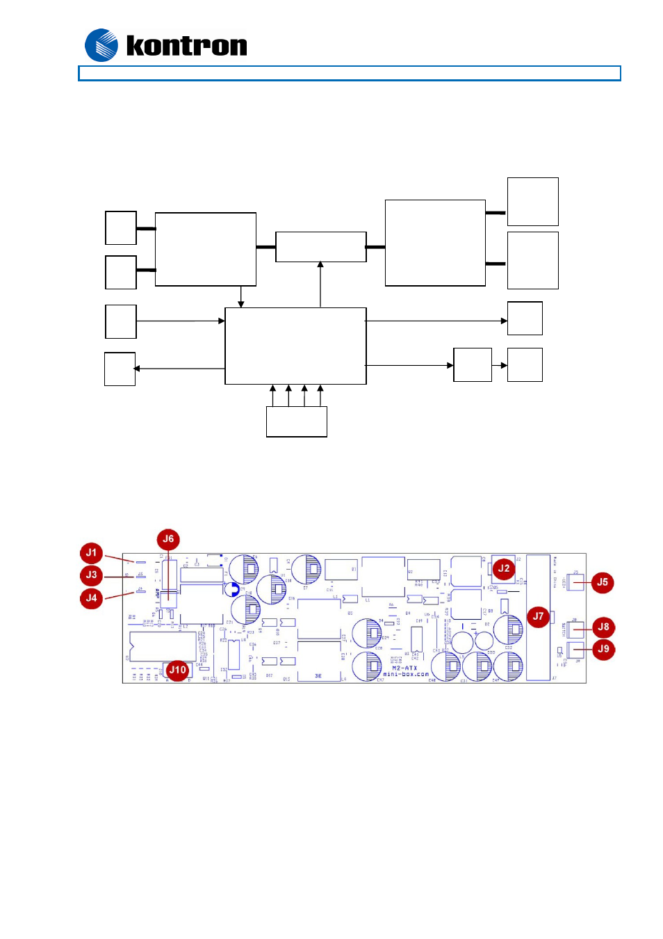
Switch Logic
10 – 25V DC/DC
converters
Protection circuit
(Filter, Fuse,
TVS, Under
voltage, reverse
voltage)
Microcontroller
and I/O interface
ATX
Power
Conn.
(J7)
ATX+12V
Conn.
(J2)
+V
(J1)
-V
(J4)
SW
(J3)
LED
(J5)
Switch
(J8)
LED
(J9)
Amp
(J6)
Jumpers
(J10)
Functional diagram
Connector position
J1 = +V
J2 = ATX+12V
J3 = SW
J4 = -V
J5 = LED
J6 = AMP
J7 = ATX Connector
J8 = Switch
J9 = Switch
J10 = Jumpers
See also other documents in the category Kontron Hardware:
- CP3003-SA uEFI BIOS (72 pages)
- CP3003-SA (36 pages)
- CP3002 (38 pages)
- CP3002-RC uEFI (64 pages)
- CP-RIO3-05 (42 pages)
- CP3002-RC (30 pages)
- CP342 (52 pages)
- CP930 (46 pages)
- CP932 (52 pages)
- CP346 (72 pages)
- CP384 (66 pages)
- CP383 (74 pages)
- CP382 (58 pages)
- CP381 (60 pages)
- CP372 (64 pages)
- CP371 (60 pages)
- CP-RIO3-04S (38 pages)
- CP390 (36 pages)
- CPS3410 (9 pages)
- CPS3402 (9 pages)
- CPS3105 (9 pages)
- CPS3101 (9 pages)
- CPS3003-SA (19 pages)
- PB-SIO4 (34 pages)
- PB-SIO4A (34 pages)
- PB-DOUT8 (34 pages)
- VMOD-2 (82 pages)
- VSBC-32 (110 pages)
- VM42 (62 pages)
- Bootstrap Loader (24 pages)
- VMP1 with Netbootloader (120 pages)
- VMP1 (106 pages)
- NetBootLoader (86 pages)
- VMP2 (142 pages)
- VMP3 (154 pages)
- CP-RIO6-923 (32 pages)
- CP-RIO6-923-F (32 pages)
- CP-RIO6-001 (28 pages)
- CP-RIO6-001-HD-VGA (46 pages)
- CP-RIO6-M (20 pages)
- CP-RIO6-B (28 pages)
- CP6925 (42 pages)
- CP6002 uEFI BIOS (76 pages)
- CP6002 IPMI (40 pages)
- CP6002 (42 pages)