1 ipmb-l link sensor, 3 field replaceable unit (fru) information, Field replaceable unit (fru) information – Kontron RTM806x User Manual
Page 24: Table 2-3 board information area
11
www.kontron.com
X
Exceed critical threshold / Error Assertion
*
Power On/Off
-
Power On
N
No change
2.7.2.1
IPMB-L Link Sensor
The RTM806X has an IPMB-L link to communicate with the processor board and other devices in the chassis
chassis IPMB-0 bus. MMC monitors the bus for any link failure and sends the bus failure event to the front
board upon the recovery occurs.
2.7.3
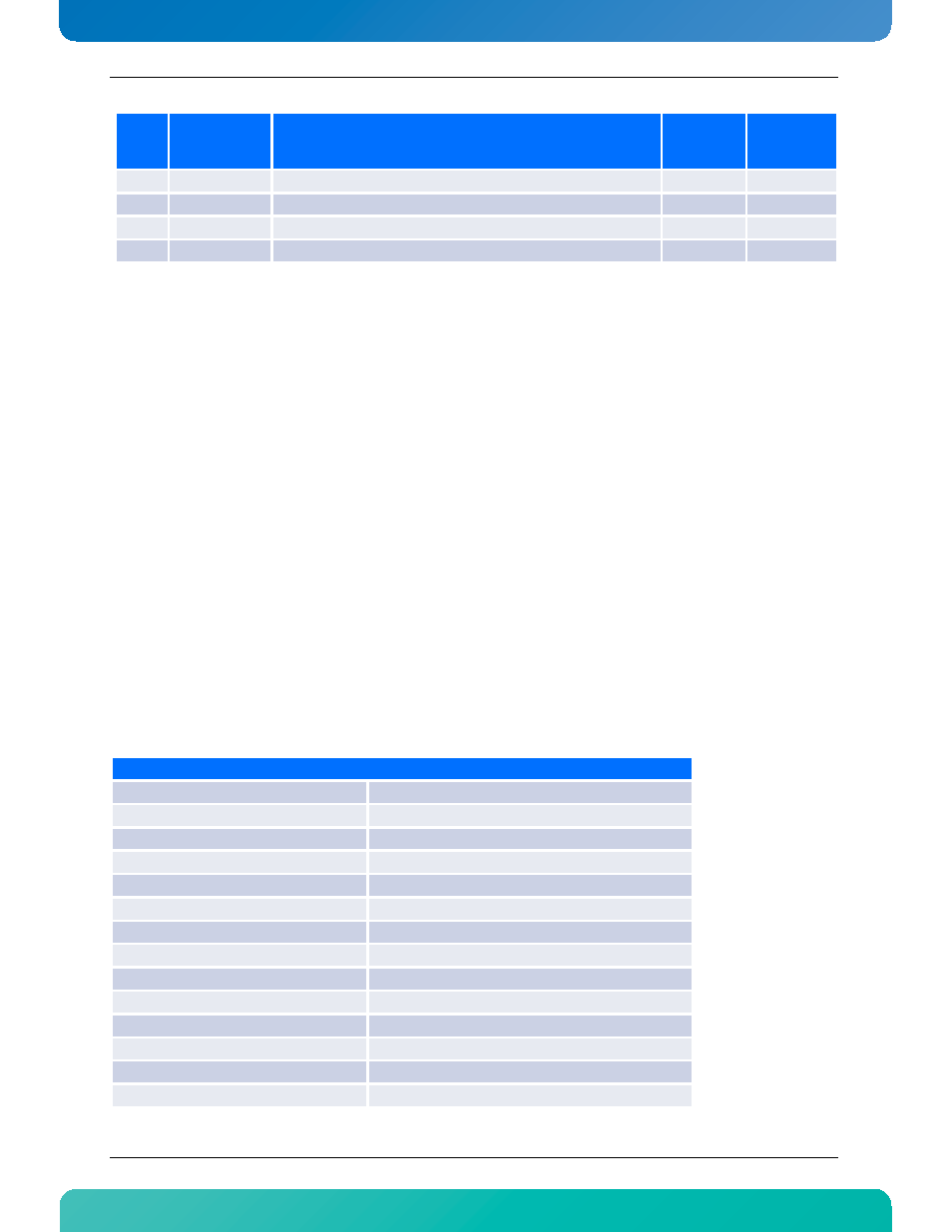
Field Replaceable Unit (FRU) Information
The FRU Information provides inventory data about the boards where the FRU Information Device is located.
The part number or version number can be read through software.
FRU information in the RTM806X includes data describing the RTM806X board similar to AMC.0 R2.0
specification requirements. This information is retrieved by the RTM, enabling reporting of board-specific
information through a standardized mechanism.
Table 2-3:Board Information Area
25
Power Good
Actual RTM power good status
-
X
26
Pwr Good HD1
Actual HD1 power good status
-
X
27
Pwr Good HD2
Actual HD1 power good status
-
X
28
Health Error
General health status
*
N
Board Information Area
Field Description
Value (hex)
Format Version
0x01
Board Area Length
*Calculated
Language code
0x00
Manufacturing Date / Time
*Based on mfg. date
Board Manufacturer type/length
*Calculated
Board Manufacturer
“Kontron”
Board Product Name type/length
*Calculated
Board Product Name
“RTM806X”
Board Serial Number type/length
*Calculated
Board Serial Number
Manufacturer S/N
Board Part Number type/length
*Calculated
Board Customer Part Number
"T5707###_R"
FRU File ID type/length
*Calculated
IPMI
sensor
ID
Sensor Name
Description (Sensor Type, Event trigger)
Scanning En-
abled under
Power State
Health LED
(Green to Am-
ber)